Facebook
 Google
 GitHub
 Linkedin
I would like to Thank All About Circuits for its existence and also apologize for my lack of knowledge and questions that I bear on everyone. My background is mainly with windows application development and automation. Ever since I discovered the microcontroller I have found myself learning more and more every day and the desire for a project. I finally found that project!...it will be used in an automotive application.
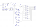
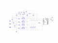
The application consist of having three +12 volt inputs from the car, these inputs will also be the main source of power. On every input the LM2671 will power, supplying +5 volts. The +12 volt will drive an opto to supply power to the microcontroller (using an opto to allow quick discharge of the power to the microcontroller for cycle purposes) and the microcontroller input. Port-B will be use to drive LED’s.
I have tested this circuit and it seems to work…I just want to see what anyone’s thought is on it. Is this even the correct way to do this, is there a better or more efficient way of accomplishing this?
Any help will be greatly appreciated.
Attachments
-
 67.1 KB Views: 30