MOD NOTE: Don't put e-mail addresses is posts or your public profile. It's guaranteed to attract spambots looking for targets. Instead, ask people to PM you (i.e., start a Conversation with you).
MOD NOTE: Don't put e-mail addresses is posts or your public profile. It's guaranteed to attract spambots looking for targets. Instead, ask people to PM you (i.e., start a Conversation with you).
Look in the upper right (if you are using the Blue schema) and you will see "Inbox". Select that and you should see something that says "Start a conversation" or something like that.
But in this case you are asking people to start a conversation with you, so you can just ask anyone that is interested to PM you. If someone does, you should receive an e-mail notification with a link that will take you straight to the conversation thread (unless you have disable those alert e-mails, which is probably not the case).
You're right.
I think you already have a PFET? (It needs to be one with a low Vgs(thr) value). As for NFETs, there are hundreds to choose from. Try a parametric search on the web-site of any stockist (e.g. Digikey, RS, Farnell). Look for something with a Vgs(thr) value <1.5V and a Rds(on) value <20mΩ.
Simulation says not, since there's no significant voltage spike.
Just wondered if you'd mind casting your eye over my selection of FETS for the Dual Polarity Pulser? They've been quite tricky to find and I want to make sure I get the right ones.
Just wondered if you'd mind casting your eye over my selection of FETS for the Dual Polarity Pulser? They've been quite tricky to find and I want to make sure I get the right ones.
These 2 might be better. They need to be what they call logic level, so they will work on 6 volts.
This applies to the gate threshold voltage.
The PFET will be a little hard to solder to since they cut the drain lead off, but you can solder to the back.
These 2 might be better. They need to be what they call logic level, so they will work on 6 volts.
This applies to the gate threshold voltage.
The PFET will be a little hard to solder to since they cut the drain lead off, but you can solder to the back.
Hi Guys, resurrecting this thread as I got round to prototyping it a couple of months ago.
Circuit works beautifully so again many thanks for all your help. I've just run into a slight issue though and am hoping you can help. I've been using a micro push switch for the prototype, however I've finally hooked up an RF receiver to get it to work remotely. I've tried both an N type Mosfet and a P type transistor to replace the switch but neither appear to provide continuous power, they appear to be pulsing the power. This prevents the reverse polarity effect from working as it should unfortunately.
When it came to a dead spot I just held down the microswitch on the prototype for 2 secs and it appeared to charge the caps and then blast the magnet round when released. I can't seem to replicate this with Mosfets or a transistor unfortunately. Maybe this is just how it is - I'm not sure sure. I'm probably making a rookie mistake here but just wondered if you had any ideas on the best switching method to use? I've reattached the schema that Alec kindly produced for reference.
Almost there with this, just need to get it over the finish line. Any help gratefully received.
If you wanted to try a single-coil version with pulse polarity reversal, here's my offering.
The switch would be provided by your RF receiver. A pulse of one polarity is generated when the switch closes and lasts for the shorter of ~0.5sec and the duration of switch closure. When the switch opens, a pulse of the opposite polarity is generated and lasts for ~0.5sec. View attachment 100327
Standby current drain is zero (plus the RF receiver draw).
Hi.
An N type FET should work as the switch, provided the RF receiver can keep the FET on or off continuously for at least the ~0.5 sec required to allow C1 or C2 to fully charge/discharge.
Can you post a schematic of the receiver output stage and how you are interfacing the receiver to the rest of the circuit?
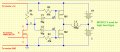
Firstly, thank you so much for getting back to me, I really appreciate it. I’ve attached a quick schema showing what I’ve added to the circuit and the config.
I think it’s a pretty standard 5v momentary type. The gate on the Mosfet is connected to the D3 pin which is channel A on the remote. Basically you hit the button and the pin goes high for the length of time you hold down the button. The Mosfet I’m using for the switch is the one below. It’s the same as I’m using in the circuit, I figured I might as well as I bought a bunch of them.
Both of these were recommended by RonV, another member on here. If you need me to provide any further info please let me know. Looking forward to your thoughts.
Think I've seen the error of my ways. The Mosfet used for the switch looks like it could be shorting out the power supply to the receiver. Do you think the attached would work or is it close but no cigar?
Just hooked it up as per the schema I posted earlier – same result unfortunately. When I press the remote the coil pulls the magnet towards it, when I release there’s no reverse polarity. When I press and hold the remote constantly the coil pulls the magnet towards it and then just pulses. Again no reverse polarity when it’s released. Strange.
I created a quick circuit using 3v, an LED and the N-channel FET as a switch connected to the receiver to test it. It turns on the LED no problem for as long as you hold the button on the transmitter fob.
Appreciate it’s tricky without knowing more about the receiver but wondered if you had any other thoughts as to what the issue could be?
What are you using as the +-3V supply? It sounds like the coil current may be pulling the voltage down too far for the circuit to work as designed. What is the coil current (or resistance)?
What are you using as the +-3V supply? It sounds like the coil current may be pulling the voltage down too far for the circuit to work as designed. What is the coil current (or resistance)?
I’m using AAA cells to power the circuit and receiver. The arrangement is 2 x battery holders each containing 2 x 1.5v cells connected in series as per the configuration in the original schema. AAAs are ideal as they are powerful and small.
As I mentioned in my original post, space is limited as all this has to fit in wood boxes 9 x 9 x 4cm, so there isn’t really space for a separate power supply for the receiver. My aim was always to use the same power source for the circuit and receiver if poss.
I’m going to hook up the receiver to a separate power supply this evening to see if it makes a difference. I’ll also try and get a read on the current draw of the coil and report back.
 Facebook
 Google
 GitHub
 Linkedin

 There is a supply voltage conflict in your setup: 5V from the receiver is connected directly to 6V from the two batteries in series.


