Facebook
 Google
 GitHub
 Linkedin
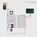
Hello, I am trying to make a breadboard design where I have a USB-C breakout board connected to an Arduino which is connected to a MOSFET and then an LED light. I want to make it so that when the USB-C cable is inserted into the breakout board it turns on the LED light and when the cable is pulled out of the breakout board it turns off the LED light. I have bought both N and P channel MOSFETS, an ARDUINO SEEED Studio XIAO SAMD21, a bunch of LED lights, A breadboard, and a 5v breadboard power supply. I would love someones help with how to conenct all of these parts to make it work properly, and how to code the ARDUINO.
Using MOSFETS and an Arduino
- Thread starter Mock10chicken
- Start date