Using microcontroller to turn on and off power supply for the LM317 (CCS)?

Thread Starter

K_Thewld

Joined Jul 25, 2017
9
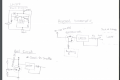
So I a working on a project where I have different devices attached to a board and they are not used at the same time. One of the devices is a laser diode that has a maximum current rating of 1.7A. Now I wanted to design a constant current source circuit using the LM317 adjustable voltage regulator. The LM317 maximum current rating is 1.5A, which is fine because I plan on driving up to 1A to the laser anyway. I have two issues: first, I have looked in the datasheet for the LM317 and on page 14 figure 18, is a schematic of the LM317 in constant current configuration but it's only 50mA). Second remember that this device will only operate by it self while the others are off, therefore I need a way of logically turning on the power source for the LM317 that's going to help it generate at least 1A. I have a logic level n-channel mosfet, PSMN022-30pl and I am using a raspberry (microcomputer) as the brains.t Looking through the LM317 datasheet, figure 23 on page 17 was the closest idea to generating higher current using a transistor, but it is not in the constant current configuration. I first was thinking of tying the mosfet drain to a 9v-12v PS, the gate tied to a GPIO to the raspberry through a low value resistor, and tying the source to the input of the LM317, but I don't believe that the LM317 can handle forcing current through the input like that. Any suggestions?

LM317 Datasheet - Here
PSMN022-30pl Datasheet - Here
 

dendad

Joined Feb 20, 2016
4,635
You are going to take the power dissipation of the LM317 into account. This is often missed by new users.
Use (supplyV - reg_o/pV) x current to work out the power dissipated by the regulator.
It will need a good heatsink and the reg tab will have to be insulated from the heatsink.
And one of the simplest ways to switch the power is to use a transistor ot FET switching a relay to supply the LM317.
 

Thread Starter

K_Thewld

Joined Jul 25, 2017
9
You are going to take the power dissipation of the LM317 into account. This is often missed by new users.
Use (supplyV - reg_o/pV) x current to work out the power dissipated by the regulator.
It will need a good heatsink and the reg tab will have to be insulated from the heatsink.
And one of the simplest ways to switch the power is to use a transistor ot FET switching a relay to supply the LM317.
I think you missing the point of the thread. I am well aware of the LM317 is going to dissipate a lot of heat, I mentioned that I looked into the datasheet, so I did see the formulas for the heat dissipation. And I do have the a heatsink for the LM317 and have a fan that will be connected to the end of the board. My concern is followed by the two issues mentioned in my previous post: 1: a constant current configuration that can produce at 1 amps. 2: I want the PSMN022 N_Channel Mosfet to be the power source for the LM317 in its constant current configuration but I don't how to add it. I will try adding a picture of a suggested schematic.
 

dendad

Joined Feb 20, 2016
4,635
Replace the 24R with a 1.2R for a start.
1A_constantCurrent.jpg
Something like this.
You can't easily just use an N channel FET to switch the input directly so having a relay may be the way to go.
 

Thread Starter

K_Thewld

Joined Jul 25, 2017
9
Replace the 24R with a 1.2R for a start.
View attachment 131662
Something like this.
You can't easily just use an N channel FET to switch the input directly so having a relay may be the way to go.
I'll keep the relay in mind. I still want to keep that constant current capability of the LM317 though, where even through the voltage fluctuates the current output stays the same.

I attached a drawing of what I was thinking of trying "Proposed Schematic". The issue I am thinking is I don't know if you can allow current to flow from the input through the output of the LM317 like that.
Also I have a drawing labeled "Bad circuit", because I had tried it while messing around with the PSMN022 and sure enough I seen something went to smoke. Wanted to know if anyone can explain why after addressing the Constant Current Logic Enabled Circuit first.
 

Attachments

dendad

Joined Feb 20, 2016
4,635
The LM 317 will work as the circuit I put up. The output current must flow through the input!
The FET will not work directly from the RasPi as the gate will not go high enough +Ve. The gate must be a few volts higher then the lead to the LM317, and that is not going to work in your circuit. The input to the LM317 must be at least laser (diodeV +1.25v + dropoutV), maybe 6V, so the gate will need to be at least 10V to run. A small NFET driving a PFET will work, but a relay as shown is pretty easy.

And the "bad circuit" just switches on to give you a short circuit across the power supply. You probably could get away with having the constant current LM317 circuit in series with the laser diode and then switching that to ground with the FET.
Do you need the laser diode to be at ground potential for any reason?
I could draw you a circuit of what I mean if you like, but maybe tomorrow as it is late at night here now.
 
Last edited:

dendad

Joined Feb 20, 2016
4,635
I couldn't get to sleep so here are a couple of ideas...

1A_constantCurrent2.jpg OOPS! the 22R should read 220R!!!!

#1 will have a 1A output when the FET is off, and about a 1.2V out when the FET is on, and that is not enough volts to flow into the laser diode, so no laser current. You may not need the series diode.

#2 is just the constant current and laser diode in series. With FET off, no light, with FET on, a beam :)
Now maybe I can get to sleep ;)
 

Thread Starter

K_Thewld

Joined Jul 25, 2017
9
I couldn't get to sleep so here are a couple of ideas...

View attachment 131665 OOPS! the 22R should read 220R!!!!

#1 will have a 1A output when the FET is off, and about a 1.2V out when the FET is on, and that is not enough volts to flow into the laser diode, so no laser current. You may not need the series diode.

#2 is just the constant current and laser diode in series. With FET off, no light, with FET on, a beam :)
Now maybe I can get to sleep ;)

Thank you for these schematics they help much. Now to test and analyze them. Thank you again
 

Thread Starter

K_Thewld

Joined Jul 25, 2017
9
The LM 317 will work as the circuit I put up. The output current must flow through the input!
The FET will not work directly from the RasPi as the gate will not go high enough +Ve. The gate must be a few volts higher then the lead to the LM317, and that is not going to work in your circuit. The input to the LM317 must be at least laser (diodeV +1.25v + dropoutV), maybe 6V, so the gate will need to be at least 10V to run. A small NFET driving a PFET will work, but a relay as shown is pretty easy.

And the "bad circuit" just switches on to give you a short circuit across the power supply. You probably could get away with having the constant current LM317 circuit in series with the laser diode and then switching that to ground with the FET.
Do you need the laser diode to be at ground potential for any reason?
I could draw you a circuit of what I mean if you like, but maybe tomorrow as it is late at night here now.

It makes sense that the current has to go through the input of the LM317, from collector through the emitter of that darlington transistor inside of it. Just my mind right now, going all over the place and questioning everything.
 

crutschow

Joined Mar 14, 2008
38,325
Since 1.2V should not generate any significant current through the Laser diode I would go with the top circuit in post #7 as it requires only one low-current transistor.
Here's an LTspice simulation of that circuit:
You can also use a small NPN transistor such as a 2N3904 for M1.

upload_2017-7-26_8-44-31.png
 
Last edited:

Thread Starter

K_Thewld

Joined Jul 25, 2017
9
Since 1.2V should not generate any significant current through the Laser diode I would go with the top circuit in post #7 as it requires only one low-current transistor.
Here's an LTspice simulation of that circuit:
You can also use a small NPN transistor such as a 2N3904 for M1.

View attachment 131672
Thank you. Will use that one. How were you able to get the LM317 into LTSPICE I tried finding it in the parts library and couldn't find it.
 

crutschow

Joined Mar 14, 2008
38,325
Here are the LM317 files:
The .sub file goes in C:\Program Files (x86)\LTC_Old\LTspiceIV\lib\sub.
The .asy file goes in C:\Program Files (x86)\LTC_Old\LTspiceIV\lib\sym\PowerProducts
 

Attachments

Top