if you follow this thread you will see iam building an inductive amplifier to amplify tones between 500hz and 3000hz, the circuit is now built but the tones aren't loud enough and there is abit of hiss in the background, any ideas how i could amplify these tones i want to listen to and reduce hiss in the background.
thakns
fred
hi,
iam building an inductive amplifier to amplify tones between 500hz and 3000hz, the circuit is now built but when tested (with headphones) the tones aren't loud enough, i can hear them just (if i use my pc speaker, which is a poor excuse for one, usb with abit of an amplifier) and there is abit of hiss in the background, any ideas how i could amplify these tones i want to listen to and reduce hiss in the background.
please note my electronics experiance is somewhat limited, it's been along time since i specified anything and iam operating on my limits
thanks
fred
this is what i had based the circuit on, i life the idea of using a filter too, where would i start?? i am trying to provide an output on detecting tones between 500hz and 3000hz
thanks for your replys
can anyone help me design a bandpass filter for my inductive amplifier,
i need to keep anything from 500hz to 3000hz and filter out everything else,
iam a bit of a beginner with my design knowledge being limited!! but i will be ok to build the circuit (hopefully!)
sorry if this appears a duplicated thread only i wanted the tittle to reflect the requirements of the project
Yeah bill. In an attempt to consolidate the multitude of threads on the same topic by the same OP, I must have been in the midst of the merge when the reply was being made. I think I now have things sorted out.
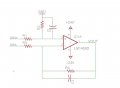
I've attached a nice active low pass filter differential amplifier circuit. It has -6dB per decade, not as great as some of the heavier duty active filters, but it wins points for amplifying and filtering at the same time.
R4 = R2
R3 = R1
Gain = R2/R1.
Bandwidth = 1/2*pi*R2*C2.
Just chain this up with another such circuit, where the first one is set to 500Hz and the next one 3000 Hz.
You can use the diff amps along the way for your amplification (if you need much power you'll have to buffer the output).
If you are driving a class A output stage and only have a +5V supply for the opamps, you can adjust the GND to be Vcc/2 and it will amplify around that as a midpoint.
Please note I just inserted some random op-amp in my schematic capture, so select an op-amp suited to your application.
im going to build the filter that Skeebopstop has specified, however what chip should i use?
the current circuit is based on an LF351, should i use one of these? Other people have commented my inductive amplifier should be based on the lm386, but im not too sure if that will give me the full bandwidth required?
Depends on what you need of it. What is the range of your input signal? do you have a dual supply or single ended to power the opamp? Were you looking to only power a weak signal (i.e. headphones)? are you doing Class A, B, or AB type amplifier?
to implement easiest, Class A, use single ended 24v supply and bias a +-10V maximum output around 12V. At which point, if your application doesn't need to be horribly exact and only drives 30mA or so, just use the provided circuit.
Im not really going to be using the headphones 'ouput' just want to provide a high output to power a small dc motor when tones beteen 500hz and 3000hz are present, the only power i have is from batteries, currently a pp3 9v battery
 Facebook
 Google
 GitHub
 Linkedin