 Facebook
 Google
 GitHub
 Linkedin
I have recently started using software FEMM to see how the magnetic flux lines flow in the magnetic core and solenoid. Now I want to change the value of current in the solenoid to see how the flux lines changes in the core. But for that I needed to do some coding the the MATLAB, but I am not getting the required simulation results.
I could be writing the sequence of the commands wrong for defining the materials and assigning them in MATLAB.
Can anyone tell me the right seqence of writing the code in MATLAB?
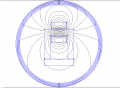
I have enclosed the required simulation result and the one that I have got while using FEMM software. Also the MATLAb code that I have written. The 'C' figure is the one that I need to get, which I did in FEMM software and the 'A' figure is the one that I have got when writing the code in MATLAB.
Moderator edit: MATLAB code added in place.
I could be writing the sequence of the commands wrong for defining the materials and assigning them in MATLAB.
Can anyone tell me the right seqence of writing the code in MATLAB?
I have enclosed the required simulation result and the one that I have got while using FEMM software. Also the MATLAb code that I have written. The 'C' figure is the one that I need to get, which I did in FEMM software and the 'A' figure is the one that I have got when writing the code in MATLAB.
Code:
close all;
%% start the FEMM software %%

openfemm;
newdocument(0);  %% 0 is for Magnetics problem
path = 'D:\FEMM\Install\femm42\';
% name_fem = 'HW3_first_trial.fem';
% mi_saveas('HW3_first_trial.fem');

%% Defining Problem

mi_probdef(0,'centimeters','planar', 1e-8, 1, 30, (0));  %mi probdef(freq,units,type,precision,depth,minangle,(acsolver))

%% Generate a dot %%

% U - core %
x1 = 0; y1 = 0;
x2 = 0; y2 = 5;
x3 = 5; y3 = 5;
x4 = 5; y4 = 0;
mi_addnode(x1,y1);
mi_addnode(x2,y2);
mi_addnode(x3,y3);
mi_addnode(x4,y4);

% Inner U Core %
x5 = 1; y5 = 0;
x6 = 1; y6 = 4;
x7 = 4; y7 = 4;
x8 = 4; y8 = 0;
mi_addnode(x5,y5);
mi_addnode(x6,y6);
mi_addnode(x7,y7);
mi_addnode(x8,y8);

% Iron Slab %
x9 = 0; y9 = -0.2;
x10 = 0; y10 = -1.2;
x11 = 5; y11 = -0.2;
x12 = 5; y12 = -1.2;
mi_addnode(x9,y9);
mi_addnode(x10,y10);
mi_addnode(x11,y11);
mi_addnode(x12,y12);

% Inner current coil %
x13 = 1.2; y13 = 2.8;
x14 = 1.2; y14 = 3.8;
x15 = 3.8; y15 = 3.8;
x16 = 3.8; y16 = 2.8;
mi_addnode(x13,y13);
mi_addnode(x14,y14);
mi_addnode(x15,y15);
mi_addnode(x16,y16);

% Outer Current Coil %
x17 = 1.2; y17 = 5.2;
x18 = 1.2; y18 = 6.2;
x19 = 3.8; y19 = 6.2;
x20 = 3.8; y20 = 5.2;
mi_addnode(x17,y17);
mi_addnode(x18,y18);
mi_addnode(x19,y19);
mi_addnode(x20,y20);

%% Generate a line %%

mi_addsegment(x1,y1,x2,y2);
mi_addsegment(x2,y2,x3,y3);
mi_addsegment(x3,y3,x4,y4);
mi_addsegment(x1,y1,x5,y5);
mi_addsegment(x4,y4,x8,y8);
mi_addsegment(x5,y5,x6,y6);
mi_addsegment(x6,y6,x7,y7);
mi_addsegment(x7,y7,x8,y8);
mi_addsegment(x9,y9,x10,y10);
mi_addsegment(x9,y9,x11,y11);
mi_addsegment(x10,y10,x12,y12);
mi_addsegment(x11,y11,x12,y12);
mi_addsegment(x13,y13,x14,y14);
mi_addsegment(x14,y14,x15,y15);
mi_addsegment(x15,y15,x16,y16);
mi_addsegment(x16,y16,x13,y13);
mi_addsegment(x17,y17,x18,y18);
mi_addsegment(x18,y18,x19,y19);
mi_addsegment(x19,y19,x20,y20);
mi_addsegment(x17,y17,x20,y20);

%% Defining Material Property

mi_addmaterial('Air',1,1,0,0,0,0,0,1,0,0,0,0,0);
mi_addmaterial('20 SWG',1,1,0,0,58,0,0,1,3,0,0,1,0.9144);
mi_addmaterial('M-19 Steel',1,1,0,0,2.03,0,0,1,0,0,0,0,0);

%% Defining the Circuit Property
mi_addcircprop('Circuit',10,1);

%% Defining Block labels

mi_addblocklabel(0.5,1);  % U Core
mi_addblocklabel(1,-1);  % Iron Slab
mi_addblocklabel(2,3);  %Inner Coil
mi_addblocklabel(2,6);  %Outer Coil
mi_addblocklabel(3,2);  %Air

%% Assigning materials to labels

% Air
mi_selectlabel(3,2);
mi_setblockprop('Air',0,1,'<None>',0,0,0);
mi_clearselected;

% Inner Coil
mi_selectlabel(2,3);
mi_setblockprop('20 SWG',0,1,'Circuit',0,0,100);
mi_clearselected;

% Outer Coil
mi_selectlabel(2,6);
mi_setblockprop('20 SWG',0,1,'Circuit',0,0,-100);
mi_clearselected;

% U Core
mi_selectlabel(0.5,1);
mi_setblockprop('M-19 Steel',0,1,'<None>',0,0,0);
mi_clearselected;

% Iron Slab
mi_selectlabel(1,-1);
mi_setblockprop('M-19 Steel',0,1,'<None>',0,0,0);
mi_clearselected;

%% Boundary condition
mi_makeABC();

%% Zoom Natural
mi_zoomnatural;

mi_saveas('HW3_first_trial.fem');
mi_analyze;
mi_loadsolution;Attachments
-
 34.5 KB Views: 8
 -
 28.2 KB Views: 11
 -
3.1 KB Views: 13


