Facebook
 Google
 GitHub
 Linkedin
Hello
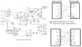
I am having trouble with a USB to Current loop converter that i am designing
I have taken Circuit Diagrams from a Serial to Current loop design and added in the USB,
But i am struggling to get any signal,
Does anyone know where i am going wrong?
I am having trouble with a USB to Current loop converter that i am designing
I have taken Circuit Diagrams from a Serial to Current loop design and added in the USB,
But i am struggling to get any signal,
Does anyone know where i am going wrong?
Attachments
-
61.4 KB Views: 17