USB Power Supply Crossed Wire Polarity

Thread Starter

JBASport

Joined Jan 15, 2019
33
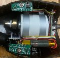
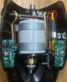
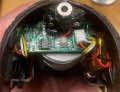
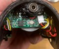
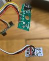
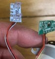
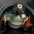
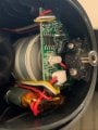
I have a problem when I connected the small motor with a wrongly wired up USB cable! When I plugged the cable into the connector, as shown in the picture, the indicator light never illuminated and a small sign of smoke appeared in the vicinity of the battery. I immediately realised something was wrong & when I tested the USB cable realised that the polarity had been wrongly assembled. Is there something I can do/check to see if it is saveable, or is the problem more likely to be terminal? Many thanks, Terry
 

Attachments

Thread Starter

JBASport

Joined Jan 15, 2019
33
It was that side, so not sure if it was the battery itself & it was only the slightest sign of smoke & only lasted about a second. Thanks
 

Ya’akov

Joined Jan 27, 2019
9,071
Keep in mind you haven't said what that is a photo of. It's not "small motor" even if there is a motor in there. I could try to guess that the thing with the captor tape is a battery, but I'd rather not guess since it could be a waste of time.

1652263904750.png
Could you explain t=what that is in the photo? Also, do you see any burnt components? If not, I don't expect we will see them in that photo. You may have to remove the PCB to see what might be on the other side.

There is a light chance the protection board on the LiPo cell smoked. One way to check that is to remove the connector (if that is the cell's connection, which it appears to be, and check for voltage on the connector. If there is nothing, the damage may be to the protection under the caption tape.
 

Jon Chandler

Joined Jun 12, 2008
1,029
Mis-wired USB cable? Were the connectors cross-wired, or did you cut off one end and connected to the wires? If the latter, always check polarity because the colors of the conductors in a cable are sometimes ignored.

Another place to be careful is with wall-wart power supplies if you cut the connector off to repurpose them. Red and black may be reversed.
 

Thread Starter

JBASport

Joined Jan 15, 2019
33
On inspection that is what seems to have been done, a new jack plug had been wrongly attached to the USB lead with the polarity of the wires reveresed. Thanks
 

Thread Starter

JBASport

Joined Jan 15, 2019
33
Keep in mind you haven't said what that is a photo of. It's not "small motor" even if there is a motor in there. I could try to guess that the thing with the captor tape is a battery, but I'd rather not guess since it could be a waste of time.

Could you explain t=what that is in the photo? Also, do you see any burnt components? If not, I don't expect we will see them in that photo. You may have to remove the PCB to see what might be on the other side.

There is a light chance the protection board on the LiPo cell smoked. One way to check that is to remove the connector (if that is the cell's connection, which it appears to be, and check for voltage on the connector. If there is nothing, the damage may be to the protection under the caption tape.
Its actually from a variable speed, function muscle massager. There doesnt seem to be any signs of burnt out components? Thanks
 

Thread Starter

JBASport

Joined Jan 15, 2019
33
Keep in mind you haven't said what that is a photo of. It's not "small motor" even if there is a motor in there. I could try to guess that the thing with the captor tape is a battery, but I'd rather not guess since it could be a waste of time.

Could you explain t=what that is in the photo? Also, do you see any burnt components? If not, I don't expect we will see them in that photo. You may have to remove the PCB to see what might be on the other side.

There is a light chance the protection board on the LiPo cell smoked. One way to check that is to remove the connector (if that is the cell's connection, which it appears to be, and check for voltage on the connector. If there is nothing, the damage may be to the protection under the caption tape.
Hi, I have taken some more images of the motor & circuit boards. There is no voltage at the connector, but suspect as the unit was completed flat and needing a charge, that would be expected. You will probably have guessed by now that my knowledge is limited, so any advice you might suggest on how to rectify how to charge the unit would be so welcome. There is no sign of anything being burnt out, but obviously the cross polarity has caused some damage. Many thanks, Terry
 

Attachments

Ya’akov

Joined Jan 27, 2019
9,071
Hi, I have taken some more images of the motor & circuit boards. There is no voltage at the connector, but suspect as the unit was completed flat and needing a charge, that would be expected. You will probably have guessed by now that my knowledge is limited, so any advice you might suggest on how to rectify how to charge the unit would be so welcome. There is no sign of anything being burnt out, but obviously the cross polarity has caused some damage. Many thanks, Terry
That’s a tough one. Things are so wedged in there it almost certainly requires removing boards to test which might be a one-way operation.

The general case is to trace the power until you don’t find it any more. Is the round silver part at the top of the last photos the power jack?
 

Thread Starter

JBASport

Joined Jan 15, 2019
33
That’s a tough one. Things are so wedged in there it almost certainly requires removing boards to test which might be a one-way operation.

The general case is to trace the power until you don’t find it any more. Is the round silver part at the top of the last photos the power jack?
Yes the silver part is the power jack socket. Should I plug in the power through the jack? Would the lithium battery be effected by charging with the wrong polarity? Many thanks.
 

Ya’akov

Joined Jan 27, 2019
9,071
If you are uncertain about the correct polarity do not plug it in! The first step will be to dtermine the correct polarity, then you can connect the power and try to trace it.

I thnk the easiest way for you to do that is to unplug the battery, then see which part of the power connector has continuity to the black wire’s pin on the battery connector, that will be the 0V (-) connection. It is very probably the outside part of the connector. Then check the supply and see in which direction you don’t read negative voltage. The red lead of the DMM will tell you the positive and the black the negative. If they don’t match what you tested on the connector you will need to rewire by swapping them on the power supply, then you can try tracing.
 

Thread Starter

JBASport

Joined Jan 15, 2019
33
If you are uncertain about the correct polarity do not plug it in! The first step will be to dtermine the correct polarity, then you can connect the power and try to trace it.

I thnk the easiest way for you to do that is to unplug the battery, then see which part of the power connector has continuity to the black wire’s pin on the battery connector, that will be the 0V (-) connection. It is very probably the outside part of the connector. Then check the supply and see in which direction you don’t read negative voltage. The red lead of the DMM will tell you the positive and the black the negative. If they don’t match what you tested on the connector you will need to rewire by swapping them on the power supply, then you can try tracing.
I have checked the USB power supply lead and this new lead is correctly configured, so will no check where the power reaches and let you know. Thanks
 

Thread Starter

JBASport

Joined Jan 15, 2019
33
The USB cable is showing 5v at the jack before coupling with the unit. When I connect to the unit I only get 1v at the white plug on the PCB board shown in the previous picture, does this sound correct to you? Thanks, Terry
 

Ya’akov

Joined Jan 27, 2019
9,071
The USB cable is showing 5v at the jack before coupling with the unit. When I connect to the unit I only get 1v at the white plug on the PCB board shown in the previous picture, does this sound correct to you? Thanks, Terry
It might. The power going to that connector is only to charge the battery. The 1V might just be the charge controller looking for the battery which isn't there. Can you measure the voltage from the battery then plug it in for a few minutes and measure it again. If it is working the battery voltage will be higher at the end.
 

Thread Starter

JBASport

Joined Jan 15, 2019
33
It might. The power going to that connector is only to charge the battery. The 1V might just be the charge controller looking for the battery which isn't there. Can you measure the voltage from the battery then plug it in for a few minutes and measure it again. If it is working the battery voltage will be higher at the end.
Hi, I have done that & the battery is still showing no sign of life. Does that likely mean that the battery has failed due to the cross polarity? There is a charging indicator light (you can see in the picture). That always used to light up on charging, no since this problem it hasn't. Would that signify a more serious problem, or am I reading too much into it. Thanks, Terry
 

Ya’akov

Joined Jan 27, 2019
9,071
Hi, I have done that & the battery is still showing no sign of life. Does that likely mean that the battery has failed due to the cross polarity? There is a charging indicator light (you can see in the picture). That always used to light up on charging, no since this problem it hasn't. Would that signify a more serious problem, or am I reading too much into it. Thanks, Terry
It seems as though something in the power path has failed. Since you think you saw smoke, it is likely something overheated and is now dead. Without seeing the other side of the PCB there is really nothing I can do in the way of help.
 

Thread Starter

JBASport

Joined Jan 15, 2019
33
It seems as though something in the power path has failed. Since you think you saw smoke, it is likely something overheated and is now dead. Without seeing the other side of the PCB there is really nothing I can do in the way of help.
Hi, I have taken another few pictures after total un-assembling the unit. The PCB is attached to the motor, but for what I can see, there is no obvious sign of damage. However I found a PCB located underneath the battery which I hadn't noticed before, could that be what has failed? I have taken a picture which hopefully shows what I mean. It looks as though it could be some form of fuse, could it be? Thanks, Terry
 

Attachments

Ya’akov

Joined Jan 27, 2019
9,071
Hi, I have taken another few pictures after total un-assembling the unit. The PCB is attached to the motor, but for what I can see, there is no obvious sign of damage. However I found a PCB located underneath the battery which I hadn't noticed before, could that be what has failed? I have taken a picture which hopefully shows what I mean. It looks as though it could be some form of fuse, could it be? Thanks, Terry
I can't tell the context from the photos, so I don't know where the power goes in or what is connected to what.

If PCB "under the battery" you are talking about is the board with the two transparent plastic parts mounted vertically on it, that is an optointerruptor. There is a photodtransitor (Q1) and an LED (D1) are facing each other. I assume it was mounted so the black wheel on the motor so there is feedback for speed control. The holes in the wheel alternately allows and prevents the light from the LED falling on the phototransistor creating a pulse train the MCU can count the frequency which is proportional to the rotation speed.
 

Thread Starter

JBASport

Joined Jan 15, 2019
33
I can't tell the context from the photos, so I don't know where the power goes in or what is connected to what.

If PCB "under the battery" you are talking about is the board with the two transparent plastic parts mounted vertically on it, that is an optointerruptor. There is a photodtransitor (Q1) and an LED (D1) are facing each other. I assume it was mounted so the black wheel on the motor so there is feedback for speed control. The holes in the wheel alternately allows and prevents the light from the LED falling on the phototransistor creating a pulse train the MCU can count the frequency which is proportional to the rotation speed.
Understood. I have taken a few more pictures to see if it might help you identify what goes where? Really appreciate your help on this. Terry
 

Attachments

Top