The tab or metal plate is directly connected to the drain of the mosfet. This means that if those two get in contact you will short out the supplying USB port.
The tab or metal plate is directly connected to the drain of the mosfet. This means that if those two get in contact you will short out the supplying USB port.
Technically yes, the shiled is better to be separate from the ground, but it won´t destroy anything etc., only the noise immunity could be a bit worse. Now that I think of it, how long is the cable run from the PC to the device?
Technically yes, the shiled is better to be separate from the ground, but it won´t destroy anything etc., only the noise immunity could be a bit worse. Now that I think of it, how long is the cable run from the PC to the device?
I will recommend my friend to use a short cable to the USB cable switch and then use the normal cables which can be up to 15feet.
I think it is the best to have the USB cable switch near the relay board and from normal. In this way one does not need to take many switching cables near the devices as we can have 2, 3 or more cameras on one Telescope pier.
Fot the LED of the optocoupler I used a 560 resistor which then gives a current of 21mA to the LED and according to the datasheet this LED works between 5mA and 24mA.
I will do my first switching test in a few minutes without shielding of the USB cable switch and see how the signal looks like. Then I will shield with some copper mesh all araound my PCB.
Later on I will send some images of the prototype. I found a good clean routing of the cables I think
Hi I just read on the TLP 521 datasheel that the typical switching current should be inbetween 1mA and 10mA and using a 10K resistor I only get 0.5mA. Will it switch ?
Well I tested it before your answer was here and guess what ?
It works directly without any problems
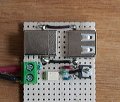
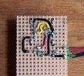
and the most interesting thing is I have a very clean image, this means as good as working without switch Now I can go into production for my Astronomy friends and make a professional PCB board. As you can see the routing is very clean and no crossings. The board size I think is acceptable. What I will do now is to shield it with the copper mesh just for protecting the circuit. I will have to be careful not to touch with the shielding the drain of the APM 3095P Mosfet. I think I will glue it onto the bard using two sided tape.
Attached images of the Prototype board and also the link to the images of Camera ON and OFF.
Again thanks a lot to everybody who helped me with this little Project
The only problem now is to make myself a component for the APM 3095P Mosfet with the correct footprint. Still do not know how to do it. The board has 2.54mm hole pattern. I will now start and try to make a component.
 Facebook
 Google
 GitHub
 Linkedin
")