Urgent please help!!!

Thread Starter

ANKuRS

Joined Jul 7, 2013
4
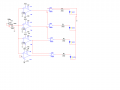
in this project, the LEDs are meant to light up with different values of the change in resistance of the variable resistor. But somethings gone wrong. Could anyone help figure out the dilemma. i have attached the circuit. please help
 

Attachments

absf

Joined Dec 29, 2010
1,968
You used 3 separate battery supplies and 2 of them have no reference to GND or 0V. Your resistors R6 R9 R10 & R11 are too high to see enough brightness on the LEDs. Your voltage divider R1 and R2 is not connected in the correct manner so there is not much voltage change to the non-inverted inputs of your op-amps..

Is this home work? :rolleyes: I have made the corrected simulation on proteus. But I am not going to post it until I see there are some efforts on your part first.....

Allen
 
Last edited:

Thread Starter

ANKuRS

Joined Jul 7, 2013
4
i made the corrections but could not figure out the voltage divider part so put on 4 different sources. could you help with the voltage divider part. the circuit i made is working but i need to put the voltage divider.
 

Thread Starter

ANKuRS

Joined Jul 7, 2013
4
i have attached the working circuit here without the voltage divider being used in the V- of the op-amp... any help there...
 

Attachments

wayneh

Joined Sep 9, 2010
18,104
All you need is ohm's law to construct a series of voltage dividers from your +12 supply. Current will flow from Vcc to ground and the voltage at each node will depend on the proportional voltage drop due to your choice of resistors. I believe you just want 4 equal resistors. The op-amps have a high impedance and can be ignored unless you use too-large resistor values and/or you need great precision.
 

Thread Starter

ANKuRS

Joined Jul 7, 2013
4
isn't there the need of 5 resistors for dividing 12V supply into 3V,6V and 9V??
Also the above circuit worked in simulation but i made the same in a breadboard and it showed some problems.
 

John P

Joined Oct 14, 2008
2,061
Where is the 5 Volts to power the 7486 coming from? If you're running that chip off 12V, then it is probably dead already. And if you get a 5V supply for it, you won't be able to drive the input pins off the output of the op amps when they go high. I think you should be able to do this job with no external logic, anyway. With some ingenuity and diodes, you should be able to make the op amps do it all.

The 714 op amp can't deal with inputs close to its high or low power supply levels, which in this case are 12V and Gnd. Resistor R2 helps in this, but I'm not sure if it will help enough. An LM324 op amp works pretty well all the way to Gnd, but it also fails at the top end.
 

SgtWookie

Joined Jul 17, 2007
22,230
The 741 opamp is a 40+ year old design, and really requires a dual ± supply in order to be able to "see" inputs near ground. At any rate, don't plan on a 741 opamp to be able to "see" inputs that are within 2v of either supply rail.
 

absf

Joined Dec 29, 2010
1,968
i have attached the working circuit here without the voltage divider being used in the V- of the op-amp... any help there...
With so much help from others, you should be able to complete your design by now...:D

So to summarize:

1. The voltage divider using R1 and R2 can be connected like this........+12V ->one end of POT , the other end of POT -> GND, R2 is not needed. The centre of POT -> opamp +input.

2. Change the 741 to something like LM324. LM339 is the proper IC for this job if you know how to use it .

3. If you must use XOR gates then use CMOS 4070 instead.

4. The reference voltage you can use wayneh and LDC3 suggestions.

Allen
 
Top