*Update on Slayer Exciter Circuit

Thread Starter

HeroKasper

Joined Dec 18, 2019
12
A few months ago i've posted in this forum in regards to my Tesla coil Slayer exciter circuit not working.
https://forum.allaboutcircuits.com/threads/tesla-coil-slayer-exciter-circuit.165658/
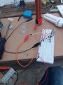
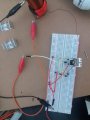
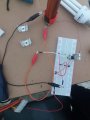
Since then i've received a lot of advices and made several changes to my circuit, my circuit now is exactly like in the photo, the circuit is supposed to be this one:
https://www.instructables.com/id/How-to-Build-a-Slayer-Exciter/
So i bought all the components aswell as a protoboard and the circuit is running on my 17V power supply.
Yet still it doesn't work, i've double checked the connections to make sure there aren't any open circuits or unconnected components but everything seems fine, but again i'm new to all this.
Any other suggestions as to why it's still not working?
 

Attachments

Sensacell

Joined Jun 19, 2012
3,432
I cannot say much about this - except that solderless breadboards are not a good choice for circuits that operate at high frequencies or high current levels.


Build it on a piece of perf board, keep leads short - as it shows in the "instrucatable"
 

Ylli

Joined Nov 13, 2015
1,086
Sure looks like the base of the transistor and the leads that are supposed to connect to it are on different points on the breadboard.
 

Wolframore

Joined Jan 21, 2019
2,609
Take a multimeter and diode check from the base to emitter and base to collector junctions. Then reverse from emitter to base And collector to base, please post reading.
 

Thread Starter

HeroKasper

Joined Dec 18, 2019
12
Take a multimeter and diode check from the base to emitter and base to collector junctions. Then reverse from emitter to base And collector to base, please post reading.
Hello! Sorry for huge delay, i did the measurements, although i'm not exactly a professional in the area here's what i got:

Positive on Base, Negative on Emitter: 660
Positive on Base, Negative on Collector: 660
Negative on Base, Positive on Emitter: 1260
Negative on Base, Positive on Collector: No input

Using the diode function on my multimeter.
I would like to add, that i have only the basic notion on electronics, and i know it's extremely hard to know what's the problem just by looking at it, but any measures you want to make i can arrange it for you.
 

Wolframore

Joined Jan 21, 2019
2,609
Positive on Base, Negative on Emitter: 660
Negative on Base, Positive on Emitter: 1260

I'm guessing this is 0.66 and 1.26 V or in millivolts either way this looks troublesome... please verify you measure while disconnected
 

Ylli

Joined Nov 13, 2015
1,086
Positive on Base, Negative on Emitter: 660
Negative on Base, Positive on Emitter: 1260

I'm guessing this is 0.66 and 1.26 V or in millivolts either way this looks troublesome... please verify you measure while disconnected
He measured in circuit. The 660 mV is the transistor B-E, the 1260 mV is the two diodes connected to the base.
 

Thread Starter

HeroKasper

Joined Dec 18, 2019
12
We need out of circuit measurements... please
Very well, i've made measurements with the transistor out of the circuit and included colector to emitter measurements:

Pos on base/neg on emitter: 660
Neg on base/pos on emitter: no input
Pos on base/neg on colector: 650
Neg on base/pos on colector: no input
Pos on colector/neg on emitter: no input
Neg on colector/pos on emitter: no input20200117_191008.jpg
 

Ylli

Joined Nov 13, 2015
1,086
None of your pictures show the top of the secondary coil. Do you have anything up there as a 'load'? Normally you would have a ball or donut, there needs to be something or there will be no current in the secondary and therefore no feedback to the base of the transistor. 3 - 4 inch aluminum foil ball should do it for testing.
 

shortbus

Joined Sep 30, 2009
10,045
I don't think all of the excess wire and the breadboard is helping him in doing this. He should be building this on perf or vero board.
 

Thread Starter

HeroKasper

Joined Dec 18, 2019
12
I don't think all of the excess wire and the breadboard is helping him in doing this. He should be building this on perf or vero board.
I've tried before, but since It wasnt working It wo
I don't think all of the excess wire and the breadboard is helping him in doing this. He should be building this on perf or vero board.
Well my first attempts were all on perf boards, but none of them worked so i was constantly having to unsolder all of the components because i couldn't figure out the issue, so i switched to breadboard but if you think it's genuinely a problem i could remake the whole thing on perf board again.
 

Thread Starter

HeroKasper

Joined Dec 18, 2019
12
None of your pictures show the top of the secondary coil. Do you have anything up there as a 'load'? Normally you would have a ball or donut, there needs to be something or there will be no current in the secondary and therefore no feedback to the base of the transistor. 3 - 4 inch aluminum foil ball should do it for testing.
That seems fair, will do, and post a picture of the result.
 
Top