unstable load resistor

Ron H

Joined Apr 14, 2005
7,063
hi everyone
first of all i want to say thanks for the replies
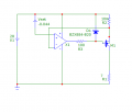
my problem is: i have unstable load resistor (range from 1 to 7 Omh) in next circuit:
https://www.dropbox.com/s/e418jfys8vdny9h/load.jpg
i need, that drain current will be constant 4A. what kind of feedback i will must put to the gate from Rload?
thanx
have you considered that with a 1Ω load, and 4 Amps, the voltage drop across the MOSFET will be 24V, and the power dissipation will be 96 Watts?:eek:
That transistor is only good for 1.6 Watts maximum.
What are you really trying to do? Give us the big picture.
 

Thread Starter

z_mx

Joined Apr 7, 2013
9
have you considered that with a 1Ω load, and 4 Amps, the voltage drop across the MOSFET will be 24V, and the power dissipation will be 96 Watts?:eek:
That transistor is only good for 1.6 Watts maximum.
What are you really trying to do? Give us the big picture.
hi
transistor can be stb120nf10 . it doesn't mater. i think that i solved this problem:
https://www.dropbox.com/s/hukpc59h1bfcud5/loadN.png
what do you think? thanx
 

kubeek

Joined Sep 20, 2005
5,796
You can´t possibly ask a to-220 package to dissipate 96W reliably.
Second thing, how do you plan to achieve those 2.5V?
What you really need is a bigger mosfer and an op-amp based current source to drive it.
Does the load need to be grounded, or can it be placed anywhere in the circuit?
 

Thread Starter

z_mx

Joined Apr 7, 2013
9
As Kubeek said, you would need an operational current source, but heat removal is going to be your big problem.
As I said, tell us the big picture. Otherwise, I'm outta here.
okay
i need to develop constant current circuit (4A) in temperature range (-45 to 85 C).
BUT my load can be from 1 to 7 ohm (random). this is a full picture.((
 
Last edited:

kubeek

Joined Sep 20, 2005
5,796
You need something along the lines of this. If you can achive the Vset and R2 to be stable along the temp range, the output will be stable too. Note the because of the drop on R2 and M1 you can never achieve full 4A for a 7Ω load.
 

Attachments

Ron H

Joined Apr 14, 2005
7,063
You need something along the lines of this. If you can achive the Vset and R2 to be stable along the temp range, the output will be stable too. Note the because of the drop on R2 and M1 you can never achieve full 4A for a 7Ω load.
That's funny. I was going to suggest something almost identical.
Why did you use 44mV as the reference? That will set the current at 4.4A.

If the application is what I think it is, I'm not sure we should be helping.:eek:
 

kubeek

Joined Sep 20, 2005
5,796
The reference is 44mV because I had to tweak it to get the current spot on, probably because of the offset voltage of the opamp.
It doesn´t ring any bells, so no idea what the application might be?
 

kubeek

Joined Sep 20, 2005
5,796
Why does it need to work just for 10 seconds? That is even more odd then the industrial temperature range, what is the rest of your college project?
 

Ron H

Joined Apr 14, 2005
7,063
hi!
thanks for everyone for the replies
i solved this problem! here is a circuit:
https://www.dropbox.com/s/4g59uc864z0jl1s/4A.jpg
Vzener=4.7V
here is a simulation:
https://www.dropbox.com/s/kde0u8tqomcukyt/4AS.jpg
as you can see: current on R3 from 3.94A to 4.1A. tolerance less than 10%.
That is a nice try. A current mirror is a huge waste of power. To get 4 amps out, you need 8 amps. Kubeek's circuit is much better.
Your simulation works because M3 and M6 are identical. Try finding two identical power MOSFETs.
They say a simulator is no better than the models you use. It is also no better than the operator. Simulators can lead to novice down the garden path.
 
Top