Facebook
 Google
 GitHub
 Linkedin
Hi all. I'm kind of new to filter design and am currently working on a project for a pulse oximeter. I wanted to simulate a 3rd Order Bessel filter with a cut off frequency of 6Hz (I wrote 3Hz a few times accidentally, but I calculated with 6Hz). I've included an attachment of the work I did to obtain resistor and capacitor values in case I went wrong there.
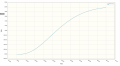
I used Circuitlab to simulate the circuit and test its step response and frequency response (I've included the plots for both). The frequency response seems relatively normal with the appropriate corner frequency. However, the step response seems quite odd with a small spike initially and then a negative voltage before rising up. Any clues as to why this is happening and where I have gone wrong?


I used Circuitlab to simulate the circuit and test its step response and frequency response (I've included the plots for both). The frequency response seems relatively normal with the appropriate corner frequency. However, the step response seems quite odd with a small spike initially and then a negative voltage before rising up. Any clues as to why this is happening and where I have gone wrong?
Last edited by a moderator: