understanding what gain means with a transistor and also a op amp?

Status
Not open for further replies.

MrAl

Joined Jun 17, 2014
13,728
MrAl - thank you for your reply.
Some comments frommy side:

It would be helpful if you would mention in detail what you mean with "other things".
Otherwise, I cannot improve/complete my answer.

May be I have misunderstood the original question (Quote: " I have been trying to get my head around what the gain means in a transistor"). But to me this sounds as if the questioner is asking "how a BJT can provide a quantity called "gain). According to my understanding, this requires a physical explanation - much more than simply to repeat a specific definition.


I am not sure if such considerations would help to answer the question

Is this an explanation or a definition?


"...my be a liitle misleading...". I am an engineer and try to classify statements only as right or wrong, sorry.
Regarding "great importance" - can you please explain this statement?
As far as I can see, the consequence of a low or high beta-ratio concerns the input resistance of the BJT unit only. And we know about very good "tricks" (circuit modifications) to make the input impedance of a gain stage rather insensitive to this BJT parameter.


I am really surprised to read that you consider again the explanations regarding the control mechanism as an "assumption" only. An assumption can be right or wrong - have you some counter arguments to my "assumption" ?
Or do you think that the BJT would be the only device in the world of electronics which functions based on two alternative physical principles?
Regarding the definition of "gain" we have two different opinions. That is a secondary problem. I can live with both definitions.
But it is very important, I think, that one knows which technical resp. physical facts are involved with the defined quantity.
(I even have seen some data sheets for FETs in which a parameter called "current gain" appears).

Summary: It is really not my goal to "convince" you of anything.
I am simply trying to answer a question as accurately as possible, taking physical reality into account.
Of course, you should not just believe me, I am only an engineer with some teaching experience.
And that is why I have referred to some globally recognized specialists for BJT-based electronics who are able to proove/explain something without using any "assumptions".
I'm sorry I just don't understand where you are going with this.

Your 'assumption' is that there is only one way to control the transistor. That I believe is too limited of an approach considering the history of engineering. Things that are not wrong can also be not as inclusive as necessary. "Three people in the USA have red shirts", that's not wrong but it's also not inclusive enough (not general enough).

But more to the point of this thread, 'gain' is already defined I don't have to define it. If you don't understand how we can say that output current divided by input current is the 'gain', then I don't know what else to tell you, and find it hard to believe you don't accept this at least in part. So the answer I have for the member who asked the question about gain of a transistor (the component itself) is that it is Iout/Iin which is amps out divide by amps in. That's what we call the current gain, and it is considered a gain, and there is a host of literature from the past that explains that. It does not matter if a solid state physicist does not like that, it's still being used today.

You seem to be trying to disprove that there is anything about a lone transistor we can call the gain. That is more than pedantic, it's just contrary to historical engineering.

So your answer is that there is no gain. My answer is that there is a gain. Ok fine with me :)

I am also not saying that these discussions are not interesting. I just hope the asker of the question gets something out of it.
Taking both ideas without knocking either one, the best would be that there are two views on this.
 

MrAl

Joined Jun 17, 2014
13,728
Hi there,

That is also interesting. The discussion we were having just before that was centered on a single, lone transistor, without any other parts. If we do add parts, then the question changes from "what is the gain of a transistor" to "what is the gain of a circuit".
Still, we probably want to answer both of those questions even though the first was the actual question I think.

It might also be interesting that sometimes we even call the output of a resistive voltage divider a 'gain'.
With the top resistor 1k and bottom resistor 1k, we sometimes say (and actually use in some calculations) the gain is 0.5 (which is 1/2).
Similarly, if the top resistor is 3k and the bottom resistor 1k, we can say the 'gain' is 0.25 (which is 1/4).
Either of these is also called an 'attenuation', but in calculations they fit into the form of the calculation the same way a gain does.
 

WBahn

Joined Mar 31, 2012
32,991
Hi there,

That is also interesting. The discussion we were having just before that was centered on a single, lone transistor, without any other parts. If we do add parts, then the question changes from "what is the gain of a transistor" to "what is the gain of a circuit".
Still, we probably want to answer both of those questions even though the first was the actual question I think.

It might also be interesting that sometimes we even call the output of a resistive voltage divider a 'gain'.
With the top resistor 1k and bottom resistor 1k, we sometimes say (and actually use in some calculations) the gain is 0.5 (which is 1/2).
Similarly, if the top resistor is 3k and the bottom resistor 1k, we can say the 'gain' is 0.25 (which is 1/4).
Either of these is also called an 'attenuation', but in calculations they fit into the form of the calculation the same way a gain does.
Attenuation is the reciprocal of gain, so a gain of 0.5 is an attenuation of 2.

This is particularly easy to see if gain is expressed in dB. A gain of -3 dB is an attenuation of 3 dB.

Because humans are not good with negative numbers (or at least that we are less prone to making mistakes if we can avoid them), we tend to talk about gain in situations were we expect it to be greater than unity (i.e., > 0 dB) and attenuation when we expect it to be less than unity (i.e., < 0 dB).
 

LvW

Joined Jun 13, 2013
2,031
I'm sorry I just don't understand where you are going with this.
Your 'assumption' is that there is only one way to control the transistor. That I believe is too limited of an approach considering the history of engineering.
My answer may be quite brief because I don't want to repeat myself.
I cannot understand why you keep talking about “assumptions” in connection with BJT control.

Here are the hard facts:
* There is much evidence (measurements, observations, experiments, effects, theoretical considerations) for the voltage control Ic=f(Vbe).
* At the same time, these facts speak against current-control !
* And, of course, there are also the statements of well-known developers (I quoted some of them earlier).
* On the other hand, there is not a single piece of evidence for current control (do you know of any?).
* No "assumptions"are necessary. I assume you are familiar with the structure of the BJT spice models? Current control?

But more to the point of this thread, 'gain' is already defined I don't have to define it. If you don't understand how we can say that output current divided by input current is the 'gain', then I don't know what else to tell you, and find it hard to believe you don't accept this at least in part.
The topic of “gain definition” is closed for me. Why are you ignoring my last post on this?
 

LvW

Joined Jun 13, 2013
2,031
It might also be interesting that sometimes we even call the output of a resistive voltage divider a 'gain'.
With the top resistor 1k and bottom resistor 1k, we sometimes say (and actually use in some calculations) the gain is 0.5 (which is 1/2).
I rather think that it does not make much sense to refer to the voltage drop in a voltage divider as “gain.”
Isn't “gain” synonymous with “amplification”?
Furthermore, in many cases we are actually dealing with undesirable voltage drops at a voltage divider (line resistance, internal source resistance....). I am afraid, it would be confusing to use the term "gain" in such a context.
 

LvW

Joined Jun 13, 2013
2,031
To everyone interested in this topic:
The question of how BJT works was discussed some time ago in the “Research Gate” forum.
In my opinion, it is interesting to read what one of the leading semiconductor developers (the late Barrie Gilbert) had to say on the subject.
The question was:
"I want to know what is the effect of base current on collect current in a BJT. Not from circuit point of view but from physics point of view"

Quote:
Barrie Gilbert
Analog Devices, Inc

Let me try to help here, by saying first that the BJT is fundamentally and
accurately a VOLTAGE-CONTROLLED CURRENT-SOURCE - which is
also known as a "TRANSCONDUCTANCE ELEMENT." In this role, it is
far more accurate and reliable than an MOS transistor, which to echo the
description by Suriavel Rao, really IS much more like a variable resistor.

Indeed, in normal (deep inversion) operation, an MOS transistor is little
more than a voltage controlled resistance. But we must understand that
this is not the same as a transconductance.

Let's look at some simple equations:
An ideal BJT behaves as follows, when the collector current is much larger than the SCALING current IS.
For now, don't worry about the fundamental structure of IS. Suffice it to
say that it is extremely small (of the order of 10-16 Amps at 300K ) and
that is it highly temperature-dependent:

IC = IS exp (VBE/VK) (operating at VCB = 0).
VBE is of course the base-emitter voltage and VK is the thermal voltage
kT/q, which is 25.85 mV at 300K. (VK is used here to avoid confusing it
with VT, reserved for the threshold voltage of an MOS transistor).

The key lessons to notice here are that (1) the dimensions of the above
equation are correct; (2) there are only two scaling factors, the current IS
and the voltage VK; (3) both of which are FUNDAMENTAL quantities in
the important sense that they’re directly related to rock-bottom physical
quantities – they’re NOT empirical; (4) the BJT equation is a statement
about a genuine transconductance:

gm = dIC / dVBE.

Now, let’s talk about base current.
As you can see from the fundamental BJT equation, there is no term in it
that depends on the base current, IB.
This current is a DEFECT due to certain processes - recombination of
carriers, partly in the bulk base region, and partly at the device surface,
where crystalline silicon meets up with the different molecular structure
of the insulator, silicon dioxide (glass).
Yes, it has a finite value, and we may be permitted to view the BJT as a
current-controlled current-source
IC = betaDCIB (large signal) or diC = betaACdB (small signal)
but these are just crude approximations because neither of these ‘betas’
is constant over the otherwise pristine 9 decades of current range (that
is a span of 1,000,000,000) over which the fundamental BJT equation is
highly reliable.
For example, a small analog-IC transistor holds closely
to this equation from an IC of about 10 pA upto 10 mA, with only small
corrections needed to the resulting VBE at each end of this range; and
varying VCB also modulates the equation.
By the way, IC designers such as myself frequently operate their BJTs
with the collectors forward biased. The math is a story for another time,
but the fact is that a typical BJT – which will operate with VCB = 0 when
connected, for example, as the diode in a two-transistor current-mirror
- will frequently operate with a collector-to-emitter voltage (VCE) of only
100-150 mV. As a clue to why this is, note that VK log (100) = 119 mV
(at 300K). Does this hint at the root of your question?

For more interaction about BJTs, I’m always available. Just e-mail me
at <snip>.
Barrie

End of Quote

Moderator edit: email address removed to avoid spam.
 
Last edited:

MrAl

Joined Jun 17, 2014
13,728
Attenuation is the reciprocal of gain, so a gain of 0.5 is an attenuation of 2.

This is particularly easy to see if gain is expressed in dB. A gain of -3 dB is an attenuation of 3 dB.

Because humans are not good with negative numbers (or at least that we are less prone to making mistakes if we can avoid them), we tend to talk about gain in situations were we expect it to be greater than unity (i.e., > 0 dB) and attenuation when we expect it to be less than unity (i.e., < 0 dB).
Ok no problem.

In control circuits a 'gain' of 10 is a gain of 10, and a gain of 0.5 is still a gain of 0.5 (1/2). It's because it works into the expessions the same way whether it is above 1, equal to 1, or less than 1, and that includes negatives less than -1, equal to -1, and between -1 and 0 inclusive.
This makes the expressions always the same.
Vout=G*Vin

This covers all the bases :)

I think that a gain of 1/2 for example can be called an attenuation factor by 2, but attenuation in general is not limited to that level of abstraction I don't think. If we say the attenuation is 1/2 for example it would be kind of unusual to think that the gain is '2' because of that. That would be a little absurd I think. When expressed in 'db' it could be different of course because sometimes we use a signed representation which is self-explanatory.
 

MrAl

Joined Jun 17, 2014
13,728
My answer may be quite brief because I don't want to repeat myself.
I cannot understand why you keep talking about “assumptions” in connection with BJT control.

Here are the hard facts:
* There is much evidence (measurements, observations, experiments, effects, theoretical considerations) for the voltage control Ic=f(Vbe).
* At the same time, these facts speak against current-control !
* And, of course, there are also the statements of well-known developers (I quoted some of them earlier).
* On the other hand, there is not a single piece of evidence for current control (do you know of any?).
* No "assumptions"are necessary. I assume you are familiar with the structure of the BJT spice models? Current control?


The topic of “gain definition” is closed for me. Why are you ignoring my last post on this?
Hi again,

Thanks for your reply, but didn't I agree with you on the solid state physics viewpoint already?
 

crutschow

Joined Mar 14, 2008
38,593
One case where the base current of a BJT is used, is in saturated switching design, where a typical base current of 1/10 the collector on-current is used to insure good saturation.
 

WBahn

Joined Mar 31, 2012
32,991
Ok no problem.

In control circuits a 'gain' of 10 is a gain of 10, and a gain of 0.5 is still a gain of 0.5 (1/2). It's because it works into the expessions the same way whether it is above 1, equal to 1, or less than 1, and that includes negatives less than -1, equal to -1, and between -1 and 0 inclusive.
This makes the expressions always the same.
Vout=G*Vin

This covers all the bases :)

I think that a gain of 1/2 for example can be called an attenuation factor by 2, but attenuation in general is not limited to that level of abstraction I don't think. If we say the attenuation is 1/2 for example it would be kind of unusual to think that the gain is '2' because of that. That would be a little absurd I think. When expressed in 'db' it could be different of course because sometimes we use a signed representation which is self-explanatory.
By pointing out that attenuation is the reciprocal of gain, I was taking exception to your statement that gain can also be called attenuation. That has the same problem as someone saying that resistance can also be called conductance -- it can't, they are reciprocals.

While is would be unusual to have an attenuation of 0.5 (meaning a gain of 2), it would be technically correct. In situations in which we normally expect attenuation, it might me sense to do that. This would especially be the case where we had a table of values, or a spreadsheet, or a program that was written in terms of attenuation and, for whatever reason, we end up with a gain.

Normally, if we anticipate or expect both gain and attenuation, we choose to use gain precisely because saying that we have a gain of 0.1 (an attenuation of 10) is less likely to be misunderstood than saying we have an attenuation of 0.1 (a gain of 10). Having said that, gains of less than unity can be misunderstood because some people will want to interpret that gain must mean that it is made bigger, and so a gain of 0.1 might be assumed to mean an increase in the signal of 10% (i.e., a gain of 1.1).
 

WBahn

Joined Mar 31, 2012
32,991
One case where the base current of a BJT is used, is in saturated switching design, where a typical base current of 1/10 the collector on-current is used to insure good saturation.
There's nothing magical about operating at a forced beta of ten -- that is merely the defacto operating point that saturation characteristics are specified at, primarily for small-signal transistors, because that was what some manufacturer chose to do some seven decades or so ago and other manufacturers chose to use the same operating point so that their claims could be compared to the other guy's claims.

For many of today's transistors it is reasonably to use a higher forced beta in saturation, both to save power but also to improve the switching speed. On the flip side, for some transistors, particularly power transistors, at high currents they don't have a beta of ten even in the active region and saturation specifications might use a forced beta of just 3 or so.
 

LvW

Joined Jun 13, 2013
2,031
One case where the base current of a BJT is used, is in saturated switching design, where a typical base current of 1/10 the collector on-current is used to insure good saturation.
I think it is misleading to say that the base current "is used...to insure good saturation".
This sounds as if the base current would be the cause of saturation.
In fact, the opposite is true.

Definition for saturation (npn case) : Vbc>0 volts.
That means: The potential Vc at the collector node is low enough (due to a large voltage drop across Rc) to open the B-C junction - in addtion to the B-E junction.
As the result, the current into the base is drastically increased (one portion to the emitter and the other portion to the collector).
At the same time (due to the 2nd portion) the current from the collector to the emitter is reduced correspondingly.

Hence, the increased base current is not the cause but the result of (and a good indication for) saturation of the BJT.
When designing the bias network (series resistor), a correspondingly large base current is therefore taken into account (rule of thumb with safety factor: "forced beta" with Ib=Ic/10).
 
Last edited:

MrAl

Joined Jun 17, 2014
13,728
I think it is misleading to say that the base current "is used...to insure good saturation".
This sounds as if the base current would be the cause of saturation.
In fact, the opposite is true.

Definition for saturation (npn case) : Vbc>0 volts.
That means: The potential Vc at the collector node is low enough (due to a large voltage drop across Rc) to open the B-C junction - in addtion to the B-E junction.
As the result, the current into the base is drastically increased (one portion to the emitter and the other portion to the collector).
At the same time (due to the 2nd portion) the current from the collector to the emitter is reduced correspondingly.

Hence, the increased base current is not the cause but the result of (and a good indication for) saturation of the BJT.
When designing the bias network (series resistor), a correspondingly large base current is therefore taken into account (rule of thumb with safety factor: "forced beta" with Ib=Ic/10).
Hi again,

That's very interesting, but I think you are pushing this voltage control thing too far.
I agree that voltage control CAN be used, and that is what I meant when I said I agree with you, but that's not the only way to interpret the operation of the bipolar transistor.

Are you saying that you don't believe any data sheets when they state the Beta values? This is what I don't get. If you think there is a problem with that then maybe you really should write to some of the component manufacturers and let them know you don't believe in Beta. Tell them why, and see what they say. Write to TI for example.

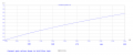
Here is an illustration of how the current 'gain' changes in a 2N2222A transistor. This is using a spice model included with MicroCap.
As shown, the current gain changes from around 196 at iB=1ma to around 153 at iB=5ma. The other current gain figures are at 1ma iB intervals.

Now my question to you is:
"Is this an illustration of current gain in a bipolar transistor or not".
To be clear, I am not asking if this is a definition of current gain, I am just asking if this is an illustration of current gain in a particular bipolar transistor.

A follow up question:
"To some other engineers besides yourself, is it *possible* that this is an illustration of current gain in a bipolar transistor".
 

Attachments

LvW

Joined Jun 13, 2013
2,031
Hi again,
That's very interesting, but I think you are pushing this voltage control thing too far.
I agree that voltage control CAN be used, and that is what I meant when I said I agree with you, but that's not the only way to interpret the operation of the bipolar transistor.
For my opinion and to avoid misunderstandings, in such a discussion we should clearly discriminate between
* Physical properties (physical working principles) of the BJT, which do not need any "interpretations", and
* specific assumptions/methods for calculation/design of ciruits which CAN be used in some particular cases (as for example current-control).

To make it clear, in this thread I only speak about the physical control mechanism of the BJT itself, which can be clearly verified and explained - based on the properties of the base barrier zone.
On the other hand, if it makes calculation easier, we CAN, of course, apply the curent-control view.
And this is a special challenge for a good engineer: To realize the difference between both principles/approaches during his work.
(Do you remember my simple example witht the resistor which "produces" a voltage V=I*R ? I always use this formula, knowing that is physically wrong).
Are you saying that you don't believe any data sheets when they state the Beta values? This is what I don't get.
Where and when did I write something similar?
In contrary, I have mentioned that the base current (and B resp. beta values) play an important role, of course, for the input impedance.
And I have mentioned the role of the base current for switching applications (bias circuitry).
Didn`t you read my comments/answers carefully?
Here is an illustration of how the current 'gain' changes in a 2N2222A transistor.
...........
Now my question to you is:
"Is this an illustration of current gain in a bipolar transistor or not".
To be clear, I am not asking if this is a definition of current gain, I am just asking if this is an illustration of current gain in a particular bipolar transistor.
I must admit that I really don`t know what you are asking and how I could answer.
Are you implying that I would deny the relationship B=Ic/Ib?

Regards
LvW
 
Last edited:
hello all

I have been trying to get my head around what the gain means in a transistor and op amps, I thought I had it and realised I don't, :( I have read numerous articles on here and numerous responses regarding what it is, and it still just isn't enough for me to get my head around, so this is my thoughts on it please correct me and ill hopefully I can get my head around it.

from what i can read it almost defies logic on how gain works, how can say an op amp gain more then the input voltage? how can it gain from thin air, and regarding a transistor say a MJ3001 where gain is explained in a datasheets, it suggests gain is how much it will take before it breaks down as the amount it takes matches the ampage rating.

what am i missing thanks in advance, might be a stupid question to some of you.
Hello, i believe this topic isn't simple either.
It's great that you found the courage to ask on what you thought was a trifling matter.
i myself get confused at times due to all the terminologies that sprout from this complex topic hehe

Some might even say 'gain' is actually a misleading term.
What's actually happening is voltage <=> current translation.

Ex. when an op amp has voltage gain, what's actually happening is that the voltage difference between the op-amp's inputs are translated to current at it's differential amplifier stage, then amplified back to voltage through a low impedance output.

Another ex. a transistor (BJT) has current gain (beta) which is just the input voltage translation to current from it's base to collector (given a common emitter setup) - i.e. input base voltage / base resistor = input current => multiply by gain (beta) => collector current

There are a lot more factors to consider when dealing with gain, but for starters
just remember it's not getting gain from thin air.
It's just voltage <=> current translation.

I hope this helps your intuition when dealing with more complex topics.
Happy learning!

Best regards,
Justin
 

LvW

Joined Jun 13, 2013
2,031
Hello, i believe this topic isn't simple either.
..............
..............
Another ex. a transistor (BJT) has current gain (beta) which is just the input voltage translation to current from it's base to collector (given a common emitter setup) - i.e. input base voltage / base resistor = input current => multiply by gain (beta) => collector current
Justin - you speak about a current "from its base to collector". Typing error?

More than that, you have written down a sequence
"input base voltage / base resistor = input current => multiply by gain (beta) => collector current"
which is in contrast to the well-known and well-proven exponential relationship (Shockleys equation) for any pn-junction
Ic=Is[exp(Vbe/Vt)-1]
which does NOT include neither an "input current" nor the beta value.

Again - the input current Ib into the base node is a kind of "side effect" which cannot be avoided (it determines the input resistance) but it has no control function in the cause-and-effect sense.

To understand the working principle of a BJT is really a pretty simple matter when you remember how the pn-junction in a diode determines the current (width modulation of the very small pn junction).
 
Last edited:

MrAl

Joined Jun 17, 2014
13,728
For my opinion and to avoid misunderstandings, in such a discussion we should clearly discriminate between
* Physical properties (physical working principles) of the BJT, which do not need any "interpretations", and
* specific assumptions/methods for calculation/design of ciruits which CAN be used in some particular cases (as for example current-control).

To make it clear, in this thread I only speak about the physical control mechanism of the BJT itself, which can be clearly verified and explained - based on the properties of the base barrier zone.
On the other hand, if it makes calculation easier, we CAN, of course, apply the curent-control view.
And this is a special challenge for a good engineer: To realize the difference between both principles/approaches during his work.
(Do you remember my simple example witht the resistor which "produces" a voltage V=I*R ? I always use this formula, knowing that is physically wrong).

Where and when did I write something similar?
In contrary, I have mentioned that the base current (and B resp. beta values) play an important role, of course, for the input impedance.
And I have mentioned the role of the base current for switching applications (bias circuitry).
Didn`t you read my comments/answers carefully?

I must admit that I really don`t know what you are asking and how I could answer.
Are you implying that I would deny the relationship B=Ic/Ib?

Regards
LvW
Hi,

Yes it sounded like you were denying B=Ic/Ib for example because you did not like calling it the 'gain'. But there is a little more to it anyway.

First, what Cruts mentioned was that we can usually use the rule for saturation where we assume a Beta of 10. That's kind of established, but you did not like that.

A little more to the main point, the model you are talking about is a limiting model, a conceptual model, not a real device. As far as I know there is no way to prevent the things I think you are ignoring like the recombination action. The model you are referring to would have no base current at all. There's no variable for base current in the Shockley equation so you can't solve for base current.

To get that equation we have to stop all types of leakage current in the transistor including the BE diode. When we do that in the BE diode, that diode becomes an open circuit (infinite impedance) while the transistor becomes completely voltage controlled. That's impossible even in a FET, but an FET is interesting as a comparison for determining what controls what.
In a bipolar, the current changes a lot more than the Vbe voltage, while in the FET the gate voltage changes a lot more than the gate current. That's why we often talk about the bipolar being current controlled while the FET is voltage controlled. Ever try measuring the change in Vbe with 10 percent collector current change? It's worth trying at least once. You'll need a more expensive meter if you want to do anything serious with that.

Furthermore, if we want to bias the transistor from +Vcc to base with a base resistor Rb, there is no way to choose that resistor with the exponential model with Vbe control unless you know of a way.
Starting from the desired Ic we can calculate Vbe using that equation (solving for Vbe) so now we would know (in theory) what Vbe has to be to get our Ic. But now we need to set Vbe with a single resistor to +Vcc. How do we set that resistor value without knowing the relationship between Ib and Vbe, which is similar to knowing the relationship between Ib and Ic, which brings us to the current gain after all. Of course we call this relationship the Beta, and why is that important.

Beta is important because Vbe can be estimated easier then actually knowing what Vbe is accurately. That's because if we assume current control we can almost ignore Vbe. If we assume voltage control through the mechanism of Vbe, then we have to set Vbe itself, which is harder to accomplish in circuits like simple amplifiers. Vbe does not vary as much as Ic or Ib that's one of the ways we define what controls what.

The reverse mode is also interesting. We can SAY that Vbe controls Ic in a super ideal case, but then what if we invert that we can say that Ic controls Vbe. The super ideal case still means finding a device that does not exist anywhere on the planet, except at absolute zero I think.

So if there is no such thing as "current gain", then there is no way to select Rb when biasing the transistor with Rb between +Vcc and the base with the emitter grounded. That would not make any sense because we all know how to do it.

Here's an idea you might like...
Set Vbe using the voltage controlled model, then set Ib based on Beta.
Once we set Vbe we know what Vcc-Vbe is, and we know what Ic is, and since Ic=Beta*Ib, we can choose Rb.
There we are using both models :)
 
Last edited:
Justin - you speak about a current "from its base to collector". Typing error?

More than that, you have written down a sequence
"input base voltage / base resistor = input current => multiply by gain (beta) => collector current"
which is in contrast to the well-known and well-proven exponential relationship (Shockleys equation) for any pn-junction
Ic=Is[exp(Vbe/Vt)-1]
which does NOT include neither an "input current" nor the beta value.

Again - the input current Ib into the base node is a kind of "side effect" which cannot be avoided (it determines the input resistance) but it has no control function in the cause-and-effect sense.

To understand the working principle of a BJT is really a pretty simple matter when you remember how the pn-junction in a diode determines the current (width modulation of the very small pn junction).
Hi! No, relationship - input base voltage translation to collector current.

Yes, Shockingley that is for pn junctions, BJTs are pnp or npn - more to consider.

Cheers,
Justin
 
Status
Not open for further replies.
Top