Understanding Voltage across resistors

Thread Starter

jericoperlas

Joined Oct 11, 2017
7
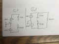
Hello, I was in an interview where they showed me circuit one and asked for the current and direction from points a to b. then the same question for circuit two. after talking to some friends they said the added third resistor doesn't change the voltage across the original two resistors.
I don't really see how, maybe it's the way the circuit is configured. any help on dumbing it down and helping me understand better why the voltage doesn't change?
MOD:rotated the image
 

Attachments

Last edited by a moderator:

Thread Starter

jericoperlas

Joined Oct 11, 2017
7
Yes. They are connected to voltage sources and the voltage (by definition) does not change with load.
but if connected to the voltage source in series, then adding a load would change the voltage across the resistor connected to the voltage source... right?

i guess the way visually the circuit looks is throwing me off. because both voltage sources are connected to ground, and both original resistors are also grounded, we can say they are parallel to the respective sources. and thus adding the load doesn't change their voltages.
 

DickCappels

Joined Aug 21, 2008
10,661
Don't think of it as series circuits. Think of it as resistors connected to ideal voltage sources that do not change with load.

For one thing, have you seen a formula that describes the change in the voltage of an ideal voltage source with load? (It is rhetorical, the only reasonable answer is "no").

The 100V voltage sources are always 100V whether there are any resistors connected or not. That is the definition of a voltage source. When you get to real voltage sources such as power supplies and batteries you might see some change with load, but this uses ideal sources.
 
Top