Facebook
 Google
 GitHub
 Linkedin
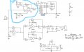
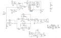
I am working on water quality monitoring system. i am using DFROBOT TDS sensor module. I want to understand the purpose of amplifier A (that attenuates signal) which is on top , is this has to do something with current. ? This sensor measure conductivity of water , and then through programming , output is converted to tds value. This module can be interfaced with arduino
Attachments
-
 52.5 KB Views: 96
Last edited: