Understanding Role of Transistor and Diode

Thread Starter

CactusPants

Joined Mar 27, 2020
6
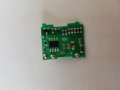
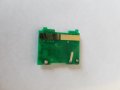
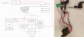
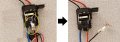
Hi. New to the forum. I'm taking a class, and for this project we were asked to tear down an electronic and analyze the circuit. I chose a cheap battery powered drill that was otherwise destined for the trash. I've torn it apart and mapped the circuit in to a rudimentary drawing (as best I can understand it). Next to it is a photo of the actual assembly. I'm having difficulty understanding what role the MOSFET transistor and the diode play (the transistor is mounted to the underside of the heatsink - you can't really see it in the photo). I have a basic understanding of what each component does, but in this everything seems to move in weird loops. The PCB mainly seems to control the variable speed of the drill. Any input to get me started?
 

Attachments

ericgibbs

Joined Jan 29, 2010
18,766
hi CP,
Welcome to AAC.
The MOSFET Gate will be driven by a PWM [pulse width Modulation] which will determine the drill rotation speed.
The current for the motor will flow from Drain to Source of the MOSFET.

As the motor coil winding current is being switched by the MOSFET, the motor winding is effectively an Inductor, so the On/Off current will create a high back EMF voltage which could damage the MOSFET.
The diode across the Motor is used to suppress/limit this back EMF and so protect the MOSFET from damage.
OK.?
E
 

Thread Starter

CactusPants

Joined Mar 27, 2020
6
Thank you for the response. It definitely lead me to a few insights.

I had to look up PWM, and again I understand the basic idea. Is the purpose of the PCB, then, to change the pulse width as the trigger is depressed? A tutorial I saw on Youtube said this is achieved with a timer chip and a potentiometer. While I don't see a potentiometer, per se, on the PCB, I believe I identified a timer chip which is accompanied by a series of resistors that are employed in different combinations as a flat spring on the trigger slides across the contact(s) on back of the PCB (see additional attached photos).

I see what you're saying about the diode's role, but without being able to follow the flow of the electrons, I don't quite understand why it's placed where it is. Looking at my slightly updated map (attached), what do you suppose the purpose of the spring-loaded contacts are that bridge only once the trigger is fully depressed? I see that the path from the MOSFET drain and source to the battery are effectively shortened (see black and blue dotted lines in middle of map) - what does this achieve?

Again, thank you for the input.
 

Attachments

ericgibbs

Joined Jan 29, 2010
18,766
hi CP,
That element looks like a 'tapped' wire wound resistor, it may be setting a PWM signal or more likely being connected in series with the motor.?
How old is the drill.?
E
 

Thread Starter

CactusPants

Joined Mar 27, 2020
6
Hello again, Eric. The drill is about 15 years old. I'm not sure which element you're referring to. If you're referring to the spring-loaded contacts, see the attached photo. Thanks.
 

Attachments

Thread Starter

CactusPants

Joined Mar 27, 2020
6
I've updated my map yet again (see attached), and I believe I've answered some of my own questions. I'm really only curious about the diode at this point. I'm trying to see how it serves the purpose you say, but I don't see how it factors in at all. Electrons seem like they would have no reason to flow through the diode in either direction.

Thanks for any insight.
 

Attachments

ericgibbs

Joined Jan 29, 2010
18,766
hi CP,
Ref the diode action.
Look up Lenz's Law, it shows that a 'back emf' [ voltage reversal] occurs when an inductor [ the motor windings] which is passing a current is rapidly switched Off.
This back emf's polarity is in a 'direction' which forward biases the diode, so the diode clamps the back emf close to the Vsupply rail, so preventing damage to the MOSFET.

The word element is used to describe the wire wound device.

E
 

Thread Starter

CactusPants

Joined Mar 27, 2020
6
Good morning and thank you for the replies.

Eric - I guess I'll just have to take Mr. Lenz's word that this diode is serving some function. Sorcery...

Boba - much thanks, but per my previous post, I'm happy with my analysis of that part of the circuit. I'm down to just wanting to better understand the diode's role. If you have anything you'd like to add in that regard, I'll gladly listen.

Have a good week and thanks again.
 

AA+

Joined Jan 4, 2014
5
An inductor likes to keep the current flowing (to support its magnetic field). When one tries to interrupt the current flow, it flows anyway. If the interrupter is a switch turning off, the current flow creates an arc, with its corresponding high voltage. The voltage is of opposite polarity to the original voltage. The "backwards" diode allows the current to keep flowing and clamps the undesired voltage to be 0.7V, the diode forward conducting voltage.

Best wishes --- Allen
 

Thread Starter

CactusPants

Joined Mar 27, 2020
6
Interesting, Allen - thanks. Is this why, in many power tools, there's a delay after releasing the trigger and cutting off power? I'd just always assumed it was the momentum of the hardware still rotating (which is most certainly a factor with a circular saw, for example).
 
Top