You don't. You never get there.
Once the angle goes beyond -90 and +90 you switch to South.
The receiver has to interpret N+90 or S-90 as heading E±degrees.
Hi,
I've just had it pointed out that a vector has a length element, so a distance along an angle.
I can see that this (AIM) is causing exchanges, so can someone give a rough idea how Vectors work, and if they get round this 'round and round' a compass problem, please?
C.
I'm afraid its back to the basics, and the basics are actualy easy, but lots of easy , gets complicated. It does my head in at least.
So the picture above, you have a line pointing in a direction,
you can think of that as your compass.
you look at it as having a direction, meassured as degrees from the "X" axis.
If we assume the length of the line is 1, keep with me here...
then you are describing a move from the centre to the end point , at an angle of say Alpha, for a length of 1
One could also say, that you have described a move along the X axis and along the Y axis,
which if you remember your sines and cosines, is
length of x is cos( alpha) and length of y is sin( alpha)
And thats all there is to it ....
Instead of an angle, you use a X and Y ,,,
To get more complicated you ask,
Well instead of the length of the line being "1" ,
we could use the length to represent how far we want to go,
say 15 meters, we make the length 15,
then what if we want to go 15 meters at an angle of 30 degrees and then 12 meters at an angle of 270 degrees,
starts to get complex in degrees and length,
now look at it in X / Y.
all we do is add all the cosines and the sines,
we move 15 * cos(30) + 12* cos (270) by 15 * sin(30) + 12 * sin(270)
3 dimensions, leave that for later for now, get confident in two dimension,
but its really just the same,
you add all the X, Y and Z directions, to come up with a final X,Y Z
We will get to vectors in a moment. Knowing vectors will provide an explanation to the next technique.
This method is to send two values, the sine of the angle and the cosine of the angle.
These values have a range from -1 to +1.
By knowing the two values the compass direction is unambiguous.
In my next post I will go into more detail on why this works, along with vectors.
Goes to show why knowing trigonometry can be important!
Hi all,
My first thought is:
With LAT, LON and ELE, we have what I imagine will suit your explanations, as we will have 3x directions to move in.
With the AIM, I don't think this affects them, as it is simply an AIM. Once the REMOTE is AIMed, then it can still fly in the 3x directions mentioned, if if it is flying sideways or any other AIM.
In mathematics, there are two kinds of numbers (besides others), scalars and vectors.
A scalar is a numerical value of magnitude such as age, weight, height, temperature, speed, angle, etc.
A vector has two values, magnitude and direction.
For example, if you wanted to describe wind conditions, you would indicate both wind speed and direction, such as 10km/h NNE.
Strictly speaking, we consider speed and angle to be scalar values.
Velocity, however, is a vector quantity, because we specify both speed and direction.
We use vectors when quantifying the motion of objects in space, automobiles, planes, boats, drones, etc.
For example, a boat is travelling 34°N @ 10kts.
We can also describe distance in terms of vectors.
A car goes East for 2km then head North for 2km.
The car's new position is 2√2 = 2 x 1.4 = 2.8km in a NE direction.
Hence we have two ways of describing the new position:
1) 2km E + 2km N
2) 2.8km N45°
(1) is called Cartesian coordinates or X-Y coordinates
(2) is called Polar coordinates or magnitude & angle.
We can convert from (1) to (2) and vice-versa using our knowledge of trigonometry.
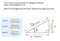
tangent(angle) = X / Y
sine(angle) = X / D
cosine(angle) = Y /D
Therefore,
X = sine(angle) x D
Y = cosine(angle) x D
The inverse is,
D x D = (X x X) + (Y x Y) = known as "Pythagoras' Theorem"
angle = inverse tangent (X / Y)
where D is the magnitude of the vector (distance from origin 0,0 to X,Y)
If your compass does'nt need recalibrated on the fly then forget about beacon.
For your rectangular grid, if you want fly by 3 meters east and 3 meters north there is two options:
1) Keep AIM to north and give same time roll to east and nick to north until you reach destination
2) Turn AIM 45 degrees from north to east and give to nick channel forward (about 4+ meters), until you reach destination
But you must aware, that on end point you have to wait different readings from sensors when flying with different options. From BASE operators point of view AIM control in degrees may be convient but in your sofware calculations you may find using other values more suitable.
Hi T,
No recalibration only comparing, so beacon, OK.
Can you explain 'nick' please?
"But you must aware, that on end point you have to wait different readings from sensors when flying with different options" What different options?
From my first understanding of the 'vector' explanations: The REMOTE compares new LAT from BASE with its present LAT, and calculate a vector. The REMOTE compares the new LON from BASE with its present LON and calculate a vector. The REMOTE compares the new ALT from BASE with its present ALT and calculate a vector. Using these 3x vectors, fly in that direction.
Re-AIM and banking, this needs more thought.
As this will mainly be used for cameras, level is good, and probably not too much hurry.
Now to re-look at 'A's messages again. I've got some homework to do, although I do remember, Archimedes, and SOHCAHTOA
C.
In RC flying is nick channel for controlling forward or backward movements and roll is for left/right movements, yaw means rudder for aircrafts.
Different options are options 1) or 2) in my post #49. Think about position of your UAV, or better pick it by your hand and look if you move this around, if you turn AIM, then compass readings are diffrent at destination point compared to this option if you not turn AIM.
AIM, is separate from the 3x vectors that I described in #50.
AIM is a DEG sent from the BASE compared with DEG READ from a COMPASS, on the REMOTE, so the REMOTE could fly in any of the combinations of the 3x directions, and not affect or be affected by them at all.
(I'm just remembering!) I say this, but I may be wrong, as the COMPASS, which is out of an Iphone 6, uses 3x Vectors to calculate it's output. (Doh! a bit more complication)
C.
Ok, no matter which options (post#49) you choose to navigate toward endpoint, the endpoint coordinates can be calculated with equal manner. Only yaw channel control uses different data based on you AIM value and compass readings.
I strongly agree with andrewmm that compass readings may be extemely unstable. I have several years ago working with one team who develop a IMU sensor network. They are struggling hard with IMU noise and simple readings averaging does not give good results, things go better only with Kalman filter routines applied. And worse thing was with compass, as it needed frequently calibrated against reference location.
Hi T,
I would generally use options 2 (post#49), but I have no experience of using this system, it's only guesswork. I can think of panning sideways, but I try to keep it basic, for now.
The compass chip is from and Iphone, and I don't have one, but I've seen phone compasses, that seemd pretty stable, is this because they ahve had a lot of work on them?
Regarding calibration, I calibrate each Compass, in a calibration box, that outputs a set of numbers, when moved in 12x different orientations, so if you're correct, I've got problems.
C.
Hi,
Thanks you for your trigonometry lessons, all was a blur until I figured out to change the letters, like this:
Obviously Pythagoras wasn't dyslexic, juggling up the letters like that
After thinkng more about it, I think it is best to stick to the square grid, as it resembles the LAT LONG system. The AIM has to be left for now, as it complicates things.
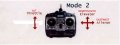
I think the Transmitter should be fixed in a NS orientation, so that forward, = N, and to the right = E. If we use my lettering for an example. Also I think the REMOTE should aim in the direction of the calculation. If BASE is at 0 LAT, 0 LON, and the forward stick is moved, then the movement of the REMOTE will be North. If the ALT stick is moved, then the ALT would be 0, and the amount of North would be A, the REMOTE should move up the calculated H, AIMing forward.
If you move ALT stick, then altitude changes but lateral coordinates (LAT,LON) are still same. On RC transmitter, if the forward and left/right controls are on the same stick then moving this stick diagonally amount of H reflects in electronics level to A and O movements allready. It calculates Pythagoras theorem for you mechanically
If you move ALT stick, then altitude changes but lateral coordinates (LAT,LON) are still same. On RC transmitter, if the forward and left/right controls are on the same stick then moving this stick diagonally amount of H reflects in electronics level to A and O movements allready. It calculates Pythagoras theorem for you mechanically
Hi T, If you move ALT stick, then altitude changes but lateral coordinates (LAT,LON) are still same. Correct.
On RC transmitter On conventional transmitters this is correct, however on this one, so far the only electronics is my BASE PCB, so no calculation, yet.
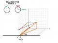
Here is an image: (I hope it's all correct?)
Move ALT 3 'O' and FWD 6 'A' and the vertical RED BLU and YEL triangle results where Yellow = 'H'
Also move RIGHT 4 and another horizontal triangle at ALT 3 results. RIGHT 4 'O' FWD 6 'A' = purple 'H'
With the combination of the 2x triangles, a new Orange 'H' needs to be calculated.
With the previous AIM DIAL, the REMOTE could rotate 360° on the spot, now it can't, it will need to go round in a circle, even if small. A bit like the top of a cylinder, being led by it's nose.
C.
Imagine if your copter sits in BASE location in coordinates ALT 0, NORTH 0, EAST 0 and you want it to move to new coordinates ALT 3, NORTH 6, EAST 4 which path is on your drawings presented by the orange line. If you give same time throttle up, nick to north and roll to east to your copter starts moving towards desired location approximately by this same orange-line path. You must only calculate the needed movement speed by each three axis if you want follow the orange-line path. For speed calculations you can use coordinate endpoints differences, for example calculate time/speed for flying from NORTH 0 to NORTH 6 an then adjust needed speed for other endpoints (for example north (nick) speed 1m/s, east (roll) speed 0.67m/s and raising (throttle ramp-up) speed 0.5m/s) . With this method you can free your REMOTE MCU from too heavy math load. Your REMOTE must check if any of coordinates endpoint is reached and hold it, while trying to reach two others. It will be not perfect method but i think it is the simplest one.
Imagine if your copter sits in BASE location in coordinates ALT 0, NORTH 0, EAST 0 and you want it to move to new coordinates ALT 3, NORTH 6, EAST 4 which path is on your drawings presented by the orange line. If you give same time throttle up, nick to north and roll to east to your copter starts moving towards desired location approximately by this same orange-line path. You must only calculate the needed movement speed by each three axis if you want follow the orange-line path. For speed calculations you can use coordinate endpoints differences, for example calculate time/speed for flying from NORTH 0 to NORTH 6 an then adjust needed speed for other endpoints (for example north (nick) speed 1m/s, east (roll) speed 0.67m/s and raising (throttle ramp-up) speed 0.5m/s) . With this method you can free your REMOTE MCU from too heavy math load. Your REMOTE must check if any of coordinates endpoint is reached and hold it, while trying to reach two others. It will be not perfect method but i think it is the simplest one.
Hi T,
I've clarified the 2x triangles image in #57
Using the top triangle first: Square root of 'O'² (16)+ 'A'²(36) = 'H' 7.21 Now we have the orange 'A' and 'O'
'H' = Square root of 'O'² (3) + 'A'² (7.21) = 7.8.
A1 = ATAN 'O'/'A' =34° which is calculated AIM. (Note if DIAL AIM is easier it still can be used)
A2 = ATAN 'O'/'A' = 21°
So AIM at angle 34° and lift at 35° for a distance of 7.8.
If I've got this completely correct, then it will be a miracle, please correct me.
I don't know how many people use NICK as ELEVATOR, but I think it would be better if we called it NS and ROLL as EW. Do you mind?
C.
Elevator and ailerons are terms for fixed wings aircaft, nick and roll are mostly used for rotorcrafts.
Why do you need calculate lift angle? Your copter does not fly that way, if you elevate copters nose you will fly backwards, unless you fly with high speed.
 Facebook
 Google
 GitHub
 Linkedin


")