You might get some help if you posted a better image. Try a screen capture instead of a picture of the screen so it doesn't have a severe moiré pattern.
What is the circuit supposed to do? I don't see any input to it! What do you know about the differential inputs of an operational amplifier? If you understand the basics, the answer is obvious.
Keith
Got it. Wouldn't it only go thru R412 (path of least resistance) and then to pin 2. Also operational amplifiers circuits as I read do not flow amperage.
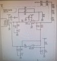
The input is the BATT+ pin at the top of the page. The circuit is a signal conditioner for the plus & minus inputs (AINP, AINN) of an analog-to-dgital converter. It appears that the BATT+ voltage can be almost 600 volts.
The input is the BATT+ pin at the top of the page. The circuit is a signal conditioner for the plus & minus inputs (AINP, AINN) of an analog-to-dgital converter. It appears that the BATT+ voltage can be almost 600 volts.
Got it. Wouldn't it only go thru R412 (path of least resistance) and then to pin 2. Also operational amplifiers circuits as I read do not flow amperage.
 Facebook
 Google
 GitHub
 Linkedin
 3.2 MB Views: 35


