 Facebook
 Google
 GitHub
 Linkedin
Hi there,
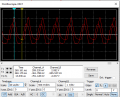
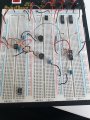
I'm currently trying to build an ultrasonic ranging module using two ultrasonic sensors Ultrasonic Tx and Rx. I've attached the schematic for the transmitter and receiver circuits as well as a photo of the actual circuit built on a breadboard. The transmitter is based round a 555 timer in astable mode. The receiver is based around an LM324n op-amp.
The issue I am having is based around the receiver. The first stage of the receiver involves a non-inverting amplifier with a gain of 11. I'm having two issues with this as the receiver is picking up ultrasonic waves from the transmitter before anything is reflected, im not sure how to solve the issue of this noise? The second issue is that the oscilloscope output is not the same as the multisim simulation.
The noise is so bad on the second amplifier that I can't really sense anything as the picked up waves from the receiver are amplified straight away.
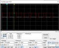
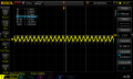
I've attached screenshots of the multisim oscilloscopes and oscilloscope traces from the Rx signal before amplification, after 1st stage and 2nd stage.
C
I'm currently trying to build an ultrasonic ranging module using two ultrasonic sensors Ultrasonic Tx and Rx. I've attached the schematic for the transmitter and receiver circuits as well as a photo of the actual circuit built on a breadboard. The transmitter is based round a 555 timer in astable mode. The receiver is based around an LM324n op-amp.
The issue I am having is based around the receiver. The first stage of the receiver involves a non-inverting amplifier with a gain of 11. I'm having two issues with this as the receiver is picking up ultrasonic waves from the transmitter before anything is reflected, im not sure how to solve the issue of this noise? The second issue is that the oscilloscope output is not the same as the multisim simulation.
The noise is so bad on the second amplifier that I can't really sense anything as the picked up waves from the receiver are amplified straight away.
I've attached screenshots of the multisim oscilloscopes and oscilloscope traces from the Rx signal before amplification, after 1st stage and 2nd stage.
C
Attachments
-
 20.4 KB Views: 9
 -
 28.6 KB Views: 8
 -
 14.2 KB Views: 6
 -
 19 KB Views: 6
 -
 46.4 KB Views: 6
 -
 52.1 KB Views: 6
 -
 46 KB Views: 6
 -
 1.8 MB Views: 6


