Ultra precision Opamp peak rectifier problem....??

Thread Starter

Himanshoo

Joined Apr 3, 2015
265
Hey guys please help me
The text says:
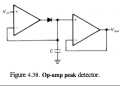
"When Vin is high the diode is FB and capacitor charges up to peak. When Vin is low the diode is RB and the capacitor tends to discharge. The reason given for this is the diode leakage currents.."

But i don't understand one thing that is that as we know that the leakage current of diode is the current that the diode will leak when a reverse voltage is applied to it and the leakage current is entire function of the reverse bias voltage applied to it...so why the text tells us that this leakage current of diode is responsible for the discharge of the capacitor...??

or if i am interpreting it right then it might be inferred as that the diode due to its leakage current provides a path for the capacitor current to discharge and get dumped in the op amp....??

Please correct me.....?

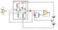
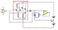
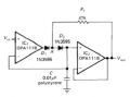
In the second figure during when Vin is high both diodes are FB and capacitor charges ....and when Vin is low then Vout which is equal to capacitor voltage will be feedback to node x via R1 thus causing zero potential across diode D2 hence eliminating leakage current of D2 ..but what happen to the leakage current of diode D1.The text say it is isolated from the capacitor but suppose if I artificially induce same Vout at node x and feedback resistor is absent then...does the leakage current of diode D1 interfere with the capacitor...??
 

Attachments

Last edited:

AnalogKid

Joined Aug 1, 2013
10,987
In the first schematic, when Vin is less than Vcap, the diode is reverse biases and leakage current flows from the cap into the output of the left side opamp. A second source of error is the input bias current of the right side opamp. Depending on the type of opamp, it might be a current sink that further discharges the cap, or it might bee a source that offsets the leakage current through the diode.

In the second schematic, if you make the changes you describe then the circuit will not work as intended. But that is true of any circuit. In this case, the extra diode and resistor are int he circuit to compensate for one particular condition, reverse biased leakage current. Because the change reduces diode D2's leakage current to zero, there is no current flow through diode D1 because there is no current.

ak
 

Thread Starter

Himanshoo

Joined Apr 3, 2015
265
and leakage current flows from the cap into the output of the left side opaamp.
You mean to say that the leakage current of the capacitor occur because of the leakage current of the diode...which provide an undesired path for the discharge current of the capacitor to flow..
 

Jony130

Joined Feb 17, 2009
5,487
In the first schematic, when Vin is less than Vcap, the diode is reverse biased, Right ?
And this means that opamp output voltage is at -15V and the cap that was previously charge to 1V. So D1 diode will see reverse voltage equal to 16V.
If so, the leakage current will start to flow, from capacitor through diode into opamp output and back to capacitor. And as you can see the current discharge the capacitor.

In the second schematic this extra resistor makes the D2 reverse voltage equal almost to 0V. And thanks to this we reduce D2 diode leakage current.
And D1 leakage current is flow from IC2 output through 47k resistor--->D1--->IC1 output.
 

kubeek

Joined Sep 20, 2005
5,794
You mean to say that the leakage current of the capacitor occur because of the leakage current of the diode...which provide an undesired path for the discharge current of the capacitor to flow..
Lekage current of a capacitor is a completely different thing from the discharge caused by the leakage current of the diode. Capacitor leakage current and diode leakage current are two very well defined terms, so I suggest you keep the word leakage only for the actual cases, and call it discharge or something else for the overall effect on the capacitor. It will make communication a bit easier.
 

Jony130

Joined Feb 17, 2009
5,487
Does the diode leakage current contains capacitor discharge current as well.....a combination of two..?
It seems so to me..?
I do not understand your question ?? Two currents?? I do not see the second current. But, yest the capacitor is discharged by a diode leakage current.
And this is not good, because we want to discharge the capacitor via some additional circuit not show here, at the time we want.
Why the leakage current will return back to the capacitor...as we know it flows from cathode to anode of diode and then into the opamp...??
Because current can only flow if we have a closed loop path for the current to flow. So the current must back to the source. In this case the charged capacitor act like a source.
 

Thread Starter

Himanshoo

Joined Apr 3, 2015
265
I do not understand your question ?? Two currents?? I do not see the second current. But, yest the capacitor is discharged by a diode leakage current.
I am also not getting that how exactly the capacitor is discharged by a diode leakage current.
I mean to say here is that ...we know that the leakage current of diode originates in the diode itself..which is far different from the capacitor discharge current ...ok till now..so the two current which i am talking about is none other than the diode leakage current and the other is the capacitor discharge current...now since the diode leakage current originates in the diode itself it flows from cathode to anode of the diode ....oK....plus what i think here may be right or wrong is that..now since the diode leakage current is flowing in the diode ..it facilitates the flow of capacitor discharge current through it (diode) because it (flow of diode leakage current) is providing a path for the capacitor discharge current to flow to the opamp...and get dumped.....

This what I think that the capacitor exactly discharged by the diode leakage current..
Please correct me...if I am wrong..
 

Jony130

Joined Feb 17, 2009
5,487
Please go back to basics.
When a diode is reverse biased it should not conduct any current at all, however, due to increased barrier potential, the free electrons on p side are dragged towards positive terminal of the battery, while holes on n side are dragged towards negative terminal of the battery. This produces a current of minority charge carriers and hence its magnitude is very very small
So as you can see the battery is discharging through diode leaking current (reverse current) and we have only one current here which circulates in the circuit:
"+"battery--->D1 from cathode to anode---->"-"battery.
Also notice that the "voltage" is needed, without the voltage current cannot flow. Also diode alone do not "produced" any current by it self.
 
Last edited:

MikeML

Joined Oct 2, 2009
5,444
...is discharging through diode leaking current (reverse current) and we have only one current here which circulates in the circuit:...
Jony, you are forgetting that any charged capacitor leaks through it's own dielectric, so there are at least two contributors to discharging the capacitor. I taught Himanshoo this in a previous thread...
 

Thread Starter

Himanshoo

Joined Apr 3, 2015
265
Also diode alone do not "produced" any current by it self.
Yes you are right that the diode alone do not produce any current by itself....voltage does matters...but I was talking in reference of this circuit...The diode leakage current is associated with the diode itself..and capacitor has its own internal leakage...as Mike in previous post said..which is a different issue for the time being..

problem is why diode's leakage current is held responsible for the capacitor discharge (directly)...
Well what i think is that and MikeML in my previous thread said that its the path.....the path which should be held responsible for the capacitor discharge...to occur..and that path is provided by the diode leakage current....

MikeML from my previous thread---->"Leakage paths from the capacitor include its own internal leakage, the input bias current, and any shunting resistors you might put there in a misguided attempt to cancel the input bias current..."

Probably the same thing said by wikipedia ....but it needs more simpification....

Wikipedia--->
"In electronics, leakage may refer to a gradual loss of energy from a charged capacitor. It is primarily caused by electronic devices attached to the capacitors, such as transistors or diodes, which conduct a small amount of current even when they are turned off. Even though this off current is an order of magnitude less than the current through the device when it is on, the current still slowly discharges the capacitor. Another contributor to leakage from a capacitor is from the undesired imperfection of some dielectric materials used in capacitors, also known as dielectric leakage. It is a result of the dielectric material not being a perfect insulator and having some non-zero conductivity, allowing a leakage current to flow, slowly discharging the capacitor"

Either they should say that the current path on which the diode leakage current flows is responsible for slow discharge of capacitor...
 

kubeek

Joined Sep 20, 2005
5,794
I don´t see what you mean, yes the path created by the diode or transistor is responsible, but that sentence is correct because the (leakage) current is what discharges the capacitor.
 

OBW0549

Joined Mar 2, 2015
3,566
Probably the same thing said by wikipedia ....but it needs more simpification....
No, it needs no simplification; it is about as clear as it could possibly be.

This stuff is really, REALLY easy to understand, Himanshoo. All you need to do is stick to the basic fundamentals:
  • The algebraic sum of currents into a circuit node is always zero;
  • All diodes leak some amount of current, however small it might be, when reverse biased;
  • All capacitors have some internal leakage resistance; for most capacitors except electrolytics this is so high that it usually can be ignored;
  • All operational amplifiers sink current into (or source current out of) their inputs, called input bias current; and
  • The rate of change of the voltage across a capacitor is equal to the current flowing into the capacitor divided by the capacitance.
Stick to those basic principles, and simple circuits like a peak detector become extremely easy to understand. This stuff is NOT complicated!
 

Jony130

Joined Feb 17, 2009
5,487
Here you have a path for the diode reverse leakage current (in red) and in blue I show you the path for capacitor leakage current.
And this circuit in the red rectangle shows an example of the internal structure of the op amp.
 

Attachments

Thread Starter

Himanshoo

Joined Apr 3, 2015
265
Here you have a path for the diode reverse leakage current (in red) and in blue I show you the path for capacitor leakage current.
And this circuit in the red rectangle shows an example of the internal structure of the op amp.
Yes I got it....
Actually I overlooked your post #8...
Now here is the bottomline...
since we all know that current whether its leakage or main current cannot flow without a source ...so its my faulty thinking which says that diode leakage current flows from cathode to anode...yes it does but current use to flow when it finds a proper loop ..and a source..so the source for diode leakage current is the R.B across it and the capacitor itself hence now it could be said that if there wont be any diode leakage current there won't be any discharge current ..since now there won't be any path ..to complete a loop for the current flow...

and now if there wont be any Rd across the capacitor in the figure in your previous post then the discharge current will flow with the diode leakage current according to the figure below
// ignore power supply currents as it is not shown........

19.opamp peak detector.png

Finally I hope so I am right now...??
 

Jony130

Joined Feb 17, 2009
5,487
I forgot to mention this in my previous post but RD resistance represent the capacitor insulation resistance or "leakage resistance". And this resistor, is responsible for the self-discharge of the capacitor. Also that IC1 in my diagram has NPN transistor at his input, so the transistors base current (input bias current) will flow into op amp input and this current will also discharge the capacitor.

As for your diagram, looks good but I do not understand what this blue "current" represents?
And it is very hard for me to accept the situation, where at the same time current flows-in and flows-out to capacitor.
 

Attachments

Thread Starter

Himanshoo

Joined Apr 3, 2015
265
And it is very hard for me to accept the situation, where at the same time current flows-in and flows-out to capacitor.
Actually blue one is the input bias current for first opamp...which I realised just now..
But it seems a paradox to me...regarding the direction of the blue arrow....
yes input bias current would be flowing from/to the opamp but then how does at the same time a current can flow in and out of the capacitor...

Please feel free to make correction in my diagram....

By the way am I some what right in deducing an inference in post 16....??
 

Jony130

Joined Feb 17, 2009
5,487
Actually blue one is the input bias current for first opamp...which I realised just now..
If so I'm ok with this.

But it seems a paradox to me...regarding the direction of the blue arrow....
yes input bias current would be flowing from/to the opamp but then how does at the same time a current can flow in and out of the capacitor...
Well, the answer to this paradox is a Kirchhoff's current law I_cap = Iblue - Ired. So, if the I_blue is larger than I_red. The blue current will provide all the red current and in the same time the blue will charge the capacitor.

By the way am I some what right in deducing an inference in post 16....??
Look good.
 
Top