UART Register Configuration

Thread Starter

Fanfire174

Joined Mar 13, 2018
240
I am working on UART configuration for pic16f877a and want to configure registers for UART ...

I have looked datasheet of pic16f877a I don't understand the correct way for the UART configuration so could anyone help to configure register.

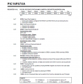
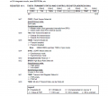
I have attached pic16f877a datasheet. page 112, 113 uart

TXSTA :Transmit Status And Control Register
RCSTA : Receive Status And Control Register
SPBRG : USART Baud Rate Generator
TXREG : USART Transmit Register. Holds the data to be transmitted on UART
RCREG ; USART Transmit Register. Holds the data received from UART

This is my configuration

Code:
 void main (void)
{
     TX9D =  0     
     TSR  =  1;     //  TSR empty
     SYNC =  1;     // Synchronous mode
     TXEN =  1;     //  Enables Transmission
     TX9  =  0 ;    //   Transmission as 8bit transmission
     CSRC =  1;
     RX9D  = 0 ;
     OERR  = 1 ;   // Overrun error
     FERR  = 0 ;   // No framing error
     ADDEN = 0 ;   // Disables address detection
     CREN  = 1 ;   // Enables continuous receive
     SREN  = 1 ;
     RX9   = 0 ;   //Selects 8-bit reception
     SPEN  = 1 ;   //Serial port enabled
     BRGH =  0     //  Low speed mode
     SPBRG = 0;
}
 

Attachments

jpanhalt

Joined Jan 18, 2008
11,087
Have you tried compiling the code? Did it work? Did you notice that FERR and OERR are read only bits? They are error flags for you to address and fix. Probably won't affect compiling, but you can leave them undefined.
 

Thread Starter

Fanfire174

Joined Mar 13, 2018
240
Have you tried compiling the code? Did it work? .
compiled code build successful
C:
//xc8 compiler
#include <xc.h>

#define _XTAL_FREQ 20000000

// BEGIN CONFIG
#pragma config FOSC = HS
#pragma config WDTE = OFF
#pragma config PWRTE = OFF
#pragma config BOREN = ON
#pragma config LVP = OFF
#pragma config CPD = OFF
#pragma config WRT = OFF
#pragma config CP = OFF
//END CONFIG
#include <xc.h>

void main(void) {

     TX9D =  0;  
     TRMT  =  1;     //  TSR empty
     SYNC  = 0;    // Asynchronous
     TXEN =  1;     //  Enables Transmission
     TX9  =  0 ;    //   Transmission as 8bit transmission
     CSRC =  1;
     RX9D  = 0 ;
     OERR  = 1 ;   // Overrun error
     FERR  = 0 ;   // No framing error
     ADDEN = 0 ;   // Disables address detection
     CREN  = 1 ;   // Enables continuous receive
     SREN  = 1 ;
     RX9   = 0 ;   //Selects 8-bit reception
     SPEN  = 1 ;   //Serial port enabled
     BRGH =  0  ;   //  Low speed mode
}
 
Last edited:

jpanhalt

Joined Jan 18, 2008
11,087
Hi,

That chip does not have "auto baud" detect.* With the 16F877A , you will need to set your baud rate. I do that even with chips that have auto baud detect. See: Section 10.1 and table 10.3 of the datasheet. Second, are you sure you want synchronous mode and USART? The chip can do both, and asynchronous is probably more common. Finally, once you set up the hardware, you will need code to do something. What are you sending to and receiving from?

John

*You can check the datasheet for the 16F1829 for a full description of that function.
 

Thread Starter

Fanfire174

Joined Mar 13, 2018
240
Hi,

That chip does not have "auto baud" detect.* With the 16F877A , you will need to set your baud rate. I do that even with chips that have auto baud detect. See: Section 10.1 and table 10.3 of the datasheet. Second, are you sure you want synchronous mode and USART? The chip can do both, and asynchronous is probably more common. Finally, once you set up the hardware, you will need code to do something. What are you sending to and receiving from?.
I want to send data from PIC to PC and receive data from PC to PIC. I would need the asynchronous mode
I have spent some time on datasheet but struggling to configure register

C:
#include <xc.h>

#define _XTAL_FREQ 20000000

// BEGIN CONFIG
#pragma config FOSC = HS
#pragma config WDTE = OFF
#pragma config PWRTE = OFF
#pragma config BOREN = ON
#pragma config LVP = OFF
#pragma config CPD = OFF
#pragma config WRT = OFF
#pragma config CP = OFF
//END CONFIG
#include <xc.h>

void main(void) {

    TRISC6 = 0; // TX Pin set as output
    TRISC7 = 1; // RX Pin set as input

    SPBRG = 19 84 6 401;
    BRGH  = 1;
    SYNC  = 0;    // Asynchronous
    SPEN  = 1;    // Enable serial port pins

    TXEN  = 1;    // enable transmission
    CREN  = 1;    // enable reception

    TX9   = 0;    // 8-bit reception selected
    RX9   = 0;    // 8-bit reception mode selected


}
void send(char message)
{
    while(TXIF==0);  // Wait till the transmitter register becomes empty
    TXIF=0;          // Clear transmitter flag
    TXREG=message;        // load the char to be transmitted into transmit reg
}


char receive()
{
    while(RCIF==0);    // Wait till the data is received
    RCIF=0;            // Clear receiver flag
    return(RCREG);     // Return the received data to calling function
}
BaudRate = Fosc/(16x(SPBRG + BRGH))

Fosc = 20000000 HZ
BaudRate = 9600

SPBRG = (Fosc / (16 * BaudRate)) - 1

SPBRG = 20, 000, 000 - 153,599 = 19, 846, 401

SPBRG = 19,846,401 and BRGH = 1
 
Last edited:

Thread Starter

Fanfire174

Joined Mar 13, 2018
240
It's time to troubleshoot code

C:
#include <xc.h>

#define _XTAL_FREQ 20000000

// BEGIN CONFIG
#pragma config FOSC = HS
#pragma config WDTE = OFF
#pragma config PWRTE = OFF
#pragma config BOREN = ON
#pragma config LVP = OFF
#pragma config CPD = OFF
#pragma config WRT = OFF
#pragma config CP = OFF
//END CONFIG
#include <xc.h>

void UART_Init(void)
{
    TRISC6 = 0; // TX Pin set as output
    TRISC7 = 1; // RX Pin set as input

    SPBRG = 130;
    BRGH  = 1;
    SYNC  = 0;    // Asynchronous
    SPEN  = 1;    // Enable serial port pins

    TXEN  = 1;    // enable transmission
    CREN  = 1;    // enable reception
 
    TX9   = 0;    // 8-bit reception selected
    RX9   = 0;    // 8-bit reception mode selected
 
}

void send(char message)
{
    while(TXIF==0);  // Wait till the transmitter register becomes empty
    TXIF=0;          // Clear transmitter flag
    TXREG=message;   // load the char to be transmitted into transmit reg
}

char receive()
{
    while(RCIF==0);    // Wait till the data is received
    RCIF=0;            // Clear receiver flag
    return(RCREG);     // Return the received data to calling function
}

void main(void)
{
 
  char i, Data[] = {"Welcome"};
  char message;

  UART_Init(void);
 
    for( i = 0; Data[i]!=0; i++)
    {
        send(Data[i]); // Transmit predefined string
    }
 

    while(1)
    {
        message = receive(); // Receive a char from serial port
        send(message);    // Transmit the received char
    }

}
 
Last edited:

JohnInTX

Joined Jun 26, 2012
4,787
Quick hits:
SPBRG should be 129 decimal (rounds down)
You don't need to manually clear RCIF and TXIF flags, that is done when you read and write RCREG and TXREG respectively.
TRIS registers should be written as a complete byte using movwf, not as individual bits.
Otherwise, it looks OK.

You can make the string output routine more useful by making it a function and passing in the address of the char array. Remember that the name of a char array is a pointer to that array. The code using an index i should work but if you're up for pointers try:
C:
void send_string(char *p)
{
   while(*p != '\0') {  //*p is the actual character that pointer p points at.  That value is 0 at the end of the string.
     send(*p);  // sends the characters in the named array until '\0'
     p++;  // bumps the pointer by one character to point to the next character
  }
}

char hi[]= {"Hello\n\r"};
char there[]={"There!\n\r"};

send_string(hi);
send_string(there);
You can tighten it up even more but it gets harder to understand.

If you have trouble getting the UART up, just send one 'U' character. That is ASCII 55h and if you have a scope handy, will toggle the serial line at the bit-rate so you can confirm your baud setting.
Have fun!
 

Thread Starter

Fanfire174

Joined Mar 13, 2018
240
Quick hits:
SPBRG should be 129 decimal (rounds down)
You don't need to manually clear RCIF and TXIF flags, that is done when you read and write RCREG and TXREG respectively.
TRIS registers should be written as a complete byte using movwf, not as individual bits.
Otherwise, it looks OK.
I ran my code but It doesn't work. I was checking with hyper terminal

any idea why it's not working
 

JohnInTX

Joined Jun 26, 2012
4,787
I ran my code but It doesn't work. I was checking with hyper terminal

any idea why it's not working
No.

But if you post your schematic and current code and what you have tested so far maybe we can go from there.

Some questions for you to answer:
  • Are you running on a simulator or actual hardware?
  • What test instruments do you have available to use?
  • Are you programming the PIC with a PICkit or some other Microchip programmer/debugger through the ISCP pins?
  • Does the code compile with NO errors and NO warnings? If not, fix that first. Hint: remove the 'void' from UART_Init(void);
  • Remove the clearing of RCIF and TXIF as noted.
  • Fix SPBRG
  • How are you getting the serial data from the PC - DB9 connector or USB-RS232 cable?
  • Do you have a suitable level-shifter like a MAX232 on the board?
  • Is HyperTerminal configured for 9600,N,8,1?
  • Does the PIC have power connected to all the Vdd and Vss pins?
  • Is MCLR/ = 1
  • Is the oscillator running? You can measure the voltage on OSC2 with a DMM and it should be around 1/2 Vdd if the oscillator is running.
  • Is the PIC running? If you have a PICkit, you can use it as a debugger and set a breakpoint somewhere in the code - at the end of INIT would be a good place. If it gets to the breakpoint, you can assume it's running.
  • You can also add a snippet of code to initialize PORTE to output some pattern on its 3 pins during init. If you can measure solid logic lows and highs on those pins, the PIC is running. If they are floating around i.e. not initialized, the PIC is not running.
When I clean up the code and run it in the simulator, it types 'Welcome' to the output window.

A quick way to test RS232 links on a PIC, assuming all else is connected and correct, is to pull MCLR/ down with a jumper to hold the PIC in reset then put a jumper across the RX and TX pins of the PIC. Hit a few keys on the terminal. If you see properly formed characters back, the basic serial link is working. If not, troubleshoot that link first.

Troubleshooting a new design always involves dividing the system into big sections first - like shorting the RX TX pins to see if the terminal is working and is the PIC running? Once you have some confidence in the hardware, you can start debugging the code.

You will need to become familiar with debugging in MPLABX using breakpoints, stepping the code, watching variables etc.

When I clean up the code and run it in the simulator, it types 'Welcome' to the output window then waits for character input.

Good luck!
 
Last edited:

jpanhalt

Joined Jan 18, 2008
11,087
I ran my code but It doesn't work. I was checking with hyper terminal
any idea why it's not working
Do you have any "one-wire" device, like a Parallax serial display? If so, I suggest trying a "send" to see what happens. If you get anything, even gibberish, you can use that as a "stake in the ground" to solve the transmission errors. I'll bet once you get those solved, solving the receive problems will be easier or disappear.

That's what I did before I had a logic analyzer. In fact, I haven't really needed that analyzer.
 

MaxHeadRoom

Joined Jul 18, 2013
30,658
There is an indepth paper on USART for the 16F,17F and 18F with programs for each, Microchip AN774.
The examples are in Assembly, but it is relatively easy to convert as they are not complex.
Max.
 

JohnInTX

Joined Jun 26, 2012
4,787
I was able to test the basic code using the MPLABX simulator and directing the UART output to an output window.
To do it:
  • Right click on the project and select Properties
  • In the Hardware Tools pane, select 'Simulator'
  • In the Categories pane, click 'Simulator'
  • In the Oscillator Options drop-down, select an Instruction Frequency of 5MHz
  • In the UART1 IO Options drop-down
  • Check Enable Uart1 IO
  • In the Output drop-down, select Window.
  • Click APPLY at the bottom.
  • Click the Debug Main Project button on the top toolbar.
  • At the bottom of the MPLABX window click the Output tab then the UART 1 Output tab.
  • You should see your 'Welcome' text.

Have fun.
 

Thread Starter

Fanfire174

Joined Mar 13, 2018
240
No

Some questions for you to answer
Are you running on a simulator or actual hardware?
I am running code on PIC development board

What test instruments do you have available to use?
I am using a hyper terminal on my laptop

Are you programming the PIC with a PICkit or some other Microchip programmer/debugger through the ISCP pins?
I have PICkit3 programmer

Does the code compile with NO errors and NO warnings? If not, fix that first. Hint: remove the 'void' from UART_Init(void);
Yes it compiles with no error give one warning ::" warning: (1273) Omniscient Code Generation not available in Free mode" I don't think this warning will effect

Remove the clearing of RCIF and TXIF as noted.?
I have done it

Fix SPBRG ?
Fixed it SPBRG = 129;

How are you getting the serial data from the PC - DB9 connector or USB-RS232 cable?
I have USB-RS232 cable

Do you have a suitable level-shifter like a MAX232 on the board?
Yes

Is HyperTerminal configured for 9600,N,8,1?
yes

Does the PIC have power connected to all the Vdd and Vss pins?
Yes

Is MCLR/ = 1 ?
I am not sure about it

Is the oscillator running? Is the PIC running? .
Yes I have been completed other project
 

JohnInTX

Joined Jun 26, 2012
4,787
Good response!

Based on my test using the simulator, the code should work if the PIC is running.
Try the sim test in #18? If that works, the problem is likely hardware or your UART setup. Have you tried the terminal test procedure outlined in #14 I.e are you sure the terminal works?
 
Top