Tyre air compressor circuit board help

Thread Starter

Maton_acoustic

Joined Aug 27, 2019
9
Hello, I’m pretty clueless when it comes to circuit boards so I’m wondering if someone can help me?

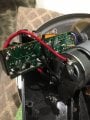
I’ve got a reasonably new digital compressor that stopped switching the motor on. I’ve proved the motor is fine by shorting the relay so it’s a circuit board issue. I’ve removed two diodes and they tested fine, I also removed the relay which switches voltage to the motor and that is working fine too. I’m not sure where to go next apart from bypassing the board completely so any help or advice would be appreciated? To me it just looks like the two diodes and a relay controlling the motor circuit. I’ve attached a picture

Many thanks
 

Attachments

MaxHeadRoom

Joined Jul 18, 2013
28,688
Not sure why the sophisticated looking board for what looks like a simple compressor!
What features is it supposed to have?
If they are not needed, you should be able to drive direct.
Max.
 

Thread Starter

Maton_acoustic

Joined Aug 27, 2019
9
Not sure why the sophisticated looking board for what looks like a simple compressor!
What features is it supposed to have?
If they are not needed, you should be able to drive direct.
Max.
Thanks for the reply. The board does also run a led light and is connected to another pcb with digital screen which deplays pressure. Which is all working normally.
It looks like I may be bypassing a couple of diodes, resistors and capacitors. Would this be ok? I can’t really work out why the relay isn’t switching when it’s on the board.
 

MaxHeadRoom

Joined Jul 18, 2013
28,688
To repair the existing board would need a little reverse-engineering and/or circuit tracing and sketch it out on paper.
Trace as to what picks the relay coil up.
Max.
 

Thread Starter

Maton_acoustic

Joined Aug 27, 2019
9
To repair the existing board would need a little reverse-engineering and/or circuit tracing and sketch it out on paper.
Trace as to what picks the relay coil up.
Max.
I’m getting 12v to + on coil and 12v to relay common. I assume the other side of the coil would be connected to ground on circuit board? Im getting 1180 ohm reading between it and the boards main ground?
 

LesJones

Joined Jan 8, 2017
4,190
The relay is probably driven by an NPN transistor or N channel mosfet. Trace the circuit to this transistor / mosfet and measure the voltage on the base if it is a transistor or gate if it is a mosfet with respect to the negative rail when the unit is in the state where the motor should be running. If it is a transistor thane expect about 0.7 volts on the base. If it is a mosfet expect between about 5 volts and 10 volts on it's gate, Does the unit switch off at some preset pressure or does it just have a simple on/off switch ?

Les.
 

MaxHeadRoom

Joined Jul 18, 2013
28,688
It would help also if you post the part numbers if you can read them off of any driver.
What features does the board claim to have, to have a relay switching the motor?
Max.
 

Dodgydave

Joined Jun 22, 2012
11,303
Find out where the Negative supply for the relay coil is going, and it will probably be a fet or npn transistor, see what is on the gate/base voltage., there could be a pressure switch at fault...
 

Thread Starter

Maton_acoustic

Joined Aug 27, 2019
9
The relay is probably driven by an NPN transistor or N channel mosfet. Trace the circuit to this transistor / mosfet and measure the voltage on the base if it is a transistor or gate if it is a mosfet with respect to the negative rail when the unit is in the state where the motor should be running. If it is a transistor thane expect about 0.7 volts on the base. If it is a mosfet expect between about 5 volts and 10 volts on it's gate, Does the unit switch off at some preset pressure or does it just have a simple on/off switch ?

Les.
I will have to look in to that. It does have on/off switch but also
 

Thread Starter

Maton_acoustic

Joined Aug 27, 2019
9
Ahh right. I didn’t even think about pressure switch. I will have to look into that. Would there be a safe, easy way to bypass that so I can just use the on off button?
 

MaxHeadRoom

Joined Jul 18, 2013
28,688
Presumably the P.S. is contact closure, if so a jumper will work.
As I mentioned previously, it should not be that a difficult circuit to map out on paper.
Max.
 
Last edited:

oz93666

Joined Sep 7, 2010
739
Otherwise it’ll probably be beyond my capabilities and end up in the bin.
Don't bin it !! just run the motor directly as Max hinted at ... Most tyre compressors don't have a pressure cut off or electronic meter ...

Manufacturers do the same with cars ... lots of complex electronics which do very little and you cannot repair , just replace ... A big solar flair , or EMP attack and we'll all be walking!
 
Top