 Facebook
 Google
 GitHub
 Linkedin
Hey y'all, probably in the wrong place to ask this question, but here goes...
I'm working on a little project, using an AD DSP controller..
trying to use a single GPIO to control a two state led..
and of course, this should apply to any microcontroller using 3.3V GPIO
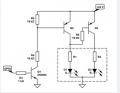
I found this circuit a while back in some online search, and did a screenshot of the schematic, and recently built up the circuit, and it almost works...

And of course, now I can't find the original article where I found the circuit. and only difference is 12V vs 24V powering the circuit.
Seems pretty straight forward, using a 3-lead/3-color LED (common cathode), power one side green, power the other side red, (and power to both yellow)...
The circuit consists of 2 pnp transistors driving the LED's, one biased on and the other off, and an npn transistor driven from a GPIO that makes the 2 pnp's change state, so should change from red to green..
But somehow there is enough leakage from the "on" transistor that the "off" state is yellow, while the "on" state makes green. ok, cool that it changes state, but the visual difference between green and yellow is sometimes hard to distinguish in bright light, would rather have a distinct green/red..
Any suggestions??
JohnR/stagekraft
I'm working on a little project, using an AD DSP controller..
trying to use a single GPIO to control a two state led..
and of course, this should apply to any microcontroller using 3.3V GPIO
I found this circuit a while back in some online search, and did a screenshot of the schematic, and recently built up the circuit, and it almost works...
And of course, now I can't find the original article where I found the circuit. and only difference is 12V vs 24V powering the circuit.
Seems pretty straight forward, using a 3-lead/3-color LED (common cathode), power one side green, power the other side red, (and power to both yellow)...
The circuit consists of 2 pnp transistors driving the LED's, one biased on and the other off, and an npn transistor driven from a GPIO that makes the 2 pnp's change state, so should change from red to green..
But somehow there is enough leakage from the "on" transistor that the "off" state is yellow, while the "on" state makes green. ok, cool that it changes state, but the visual difference between green and yellow is sometimes hard to distinguish in bright light, would rather have a distinct green/red..
Any suggestions??
JohnR/stagekraft
Attachments
-
 19.9 KB Views: 29


