Two 4 kinds ±5~15V fixed power as ±5V, ±9V, ±12V, ±15V.

Thread Starter

ScottWang

Joined Aug 23, 2012
7,398
2 sets and 4 kinds ±5~15V fixed dual power supplies as ±5V, ±9V, ±12V, ±15V.

This is a two separated fixed positive and negative dual power supplies: this power has been used for over 18 years (before 1995)

1) Vout +5V, 0V, -5V, The maximum current was around 870 mA/dc when I used a 1.4A transformer.

2) Vout +15V, +12V, +9V, 0V, -9V, -12V, -15V, The maximum current will less than 480 mA, when I used 0.8A transformer, about the ±10V, that's used two sets of three 1N4007 diodes connected in series to the ±12V.

3) The 78xx and 79xx series, generally the input voltage must be greater than the output voltage of 2.5V or more, to obtain a stable output voltage, in this case was used 3V.

4) The inputs of 7809,7812 can be connected to the input of 7815.

5) The inputs of 7909,7912 can be connected to the input of 7915.

6) There are no names and no numbers on the transformer, the label on the circuit diagram was created by me.

If you only use a single power supply, because the two power supplies are independent, it can be obtained many different voltages when they are through a cascaded method.

1) The values of voltage can be combined as 3,5,6,8,9,10,11,12,13,14,15,17,18,19,20,21,23,24,25,26,27,28, 29,30,31,32,34,35,37,40 volts.
If the power output was combined and not the standard output then the current could be less than 50 mA, but that is enough for the op-amp applications.

2) Usually the ground terminal of two power supplies, they were connected by an external wire and became a common ground, if needed for other purposes then they can be separated.

This power was used by the standard voltage regulator IC, 78xx and 79xx, so it is very convenient, the wiring is very simple, I took a universal board and soldered the parts directly, and in the practical application also very extensive, such as TTL, CMOS, OP AMP, general experimental of transistor circuits, etc..., it can be competent.

The arrangements of the actual output terminal can be seen on the panel as below, I didn't use the power LED indicators in the beginning, but I added the positive power LED indicators later, I also reserved the negative power LED indicators.

When you watch the circuit, if you find the circuit has a disconnection phenomenon, that is the browser or screen or computer software caused that, there is no problem in the circuit, if you using ACDSEE or other graphics software to see then it will be normal.

▼01-The circuit diagram of the Power Supplies.

▼02-The appearance of Power Supply.


▼03. Front Panel.


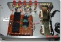
▼ 04. The internal structure A:± 5V rectifier, filter, 7805, 7905 IC regulator board - parts side.


▼ 05. The internal structure B:± 5V rectifier, filter, 7805, 7905 IC regulator board - solder side.


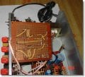
▼ 06. The internal structure C: plus and minus ±9V, ±12V, ±15V rectifier, filter, 7809, 7812, 7815, 7909, 7912, 7915 IC regulator board.


Scott Wang's Blog.
 

Attachments

Last edited:

Georacer

Joined Nov 25, 2009
5,182
Nice packaging! Can you talk a bit about the actual, accurate voltage levels that you achieved? Also, what size of heatsinks do you recommend?

Also, please give a fuse rating.
 

bloguetronica

Joined Apr 27, 2007
1,541
Nice project, and very useful indeed. However, I really recommend you to connect all the regulator inputs to the unregulated rails, instead of the cascaded configuration you've used, unless you only need 1A of distributed total corrent, and not 1A for each output. Of course my suggestion would imply larger heatsinks for the 12V regulators, and especially for the 9V regulators, as dissipated power follows the equation:

Preg = (Vi - Vo) / Ireg​

A larger transformer would be in order as well.
 

Thread Starter

ScottWang

Joined Aug 23, 2012
7,398
Nice packaging! Can you talk a bit about the actual, accurate voltage levels that you achieved? Also, what size of heatsinks do you recommend?

Also, please give a fuse rating.
Hi Georacer:
>accurate voltage levels that you achieved?
Because the output of this power is fixed and no V_meter or A_meter, so I didn't measure it, what do you want me to measure with, please tell me more clearly?

The size of heat sink -
Because I'm not reached to the Imax rating of 78xx for what I used, and the size of heat sink have some relation with operation time, and I didn't used it for 4 hrs continuing, I also have some other power has more current, so the size of this power as :
+7809,+7812,+7815,-7809,-7812,-7815 : Size - L21(mm) x W18(mm) x H15(mm)
+7805,-7905 : Size - Size - L21(mm) x W18(mm) x H15(mm)

The better size is using as:
+7805,-7905 : Size - L30(mm) x W50(mm) x H21(mm)

Or the best size is using as:
+7805,-7905 : Size - L50(mm) x W50(mm) x H21(mm)

The fuse Imax rating :
(870mA x 2) + (500mA x 2) = 2.74A
3A for DC side.
3.5A or more for AC110V/220V AC side.

------------------------------------------------------
If using the Imax rating of 78xx,79xx - output 1.5Adc.
The Imax of transformers should be using 2.5A or more.
And the Rectifiers also need to used 3A, whatever using the Rectifier diodes or bridge Rectifier.

The size of heat sink as:
Size : L50(mm) x W50(mm) x H21(mm)

At least the size as this:
Size : L30(mm) x W50(mm) x H21(mm)

The fuse Imax rating :
(1.5A x 2) + (1.5A x 2) = 6A
6A for DC side.
10A for AC110V/220V AC side.


If you think that I should provide some more infos, just tell me then I will do what I can do.
 

Thread Starter

ScottWang

Joined Aug 23, 2012
7,398
Nice project, and very useful indeed. However, I really recommend you to connect all the regulator inputs to the unregulated rails, instead of the cascaded configuration you've used, unless you only need 1A of distributed total corrent, and not 1A for each output. Of course my suggestion would imply larger heatsinks for the 12V regulators, and especially for the 9V regulators, as dissipated power follows the equation:

Preg = (Vi - Vo) / Ireg​

A larger transformer would be in order as well.
Because this power was built it for the light current circuit as simple TTL, BJT, CMOS experiments, so I build it as easy as I can, and during that time I was lived in the countryside, it's not easy to buy some parts, and I also preparing some other powers for more current, and they made by kits.

I did considered the power dissipated before, but I decided to do the cascaded configuration, and I also thought that maybe I'm not use the 9V,12V,15V at the same time.

Maybe next times that I will using some switches to do it.
 

neonharp

Joined May 10, 2015
12
Because this power is built it for the light current circuit as simple TTL, BJT, CMOS experiments, so I build it as easy as I can, and during that time that I lived in the countryside, it's not easy to buy some parts, and I also preparing some other powers for more current, and they made by kits.

I did considered the dissipated power before, but I decided to do the cascaded configuration, and I also thought that maybe I'm not use the 9V,12V,15V at the same time.

Maybe next times that I will using some switches to do it more complicated as another power, I will also post the other powers on this forum, then you can see them, but I need some more time to translate them to english.
Yes , the 78xx & 79xx regulators have been " tried and true " for many years , they do an excellent job , and don't cost much . There are a lot of options as far as building a bench power supply similar to this one , it just depends on your individual needs as far as how you intend to use it . Since you have a common ground , you could mount them all on a single larger heat-sink . If you don't need all of the outputs at once , as you said , you could add switches and just have one set of output connector jacks . Voltmeters on the outputs would be a nice addition . they aren't real expensive . Here is one vendor , there are many others :
http://www.circuitspecialists.com/lcd-panel-meters
There is a newer line of IC's available that are similar to the 78xx/79xx series , but are switch-mode and don,t require a heat-sink
Cheers , take care , and have a good day !
 

Thread Starter

ScottWang

Joined Aug 23, 2012
7,398
Yes , the 78xx & 79xx regulators have been " tried and true " for many years , they do an excellent job , and don't cost much . There are a lot of options as far as building a bench power supply similar to this one , it just depends on your individual needs as far as how you intend to use it . Since you have a common ground , you could mount them all on a single larger heat-sink . If you don't need all of the outputs at once , as you said , you could add switches and just have one set of output connector jacks . Voltmeters on the outputs would be a nice addition . they aren't real expensive . Here is one vendor , there are many others :
http://www.circuitspecialists.com/lcd-panel-meters
There is a newer line of IC's available that are similar to the 78xx/79xx series , but are switch-mode and don,t require a heat-sink
Cheers , take care , and have a good day !
Thanks for the info about the meters, I didn't use them because I want the case can be smaller, what you suggested and why I was not use the single larger heat-sink, because I just want it to be more simply and also the current of this power is not that much, the heat sink just prepared and not real needed all the time, as my some other powers have the black big heat sinks, your opinion maybe could use it in other projects, thanks.
 

neonharp

Joined May 10, 2015
12
Thanks the info about the meters, I didn't use them because I want the case can be smaller, what you suggested and why I was not use the single larger heat-sink, because I just want it to be more simply and also the current of this power is not that much, the heat sink just prepared and not real needed all the time, as my some other powers have the black big heat sinks, your opinion maybe could use it in other projects, thanks.
Another thought or two about your circuit . Unless there is a problem with the 5V supply regulators being connected to the same ground as the others , they could be fed from the same transformer/rectifier as the others . You don't need so many LED's to indicate that power is good . Since the regulators are cascaded , you should just need LED indicators for the positive and negative of the lowest voltage . If the 15 V isn't working , then the 12V won't be working , and so forth on down the line .

Cheers , take care , and have a good day !!
 

Thread Starter

ScottWang

Joined Aug 23, 2012
7,398
Another thought or two about your circuit . Unless there is a problem with the 5V supply regulators being connected to the same ground as the others , they could be fed from the same transformer/rectifier as the others . You don't need so many LED's to indicate that power is good . Since the regulators are cascaded , you should just need LED indicators for the positive and negative of the lowest voltage . If the 15 V isn't working , then the 12V won't be working , and so forth on down the line .

Cheers , take care , and have a good day !!
This power were separated for two parts and the ground can be separate any time, I was connected two ground together, because I almost use them in the same ground, when I need to use in different ground then I can separate them, and they are complete isolated.

About the led indicators that I have to try, if they really working together, when I build the similar way at next time, maybe I can use it, thanks.
 

panic mode

Joined Oct 10, 2011
2,736
2 sets and 4 kinds ±5~15V fixed dual power supplies.
... The values of voltage can be combined as 3,5,6,8,9,10,11,12,13,14,15,17,18,19,20,21,23,24,25,26,27,28, 29,30,31,32,34,35,37,40 volts.
since both stages are floating, one can certainly combine them to get sum of voltages.
but they are all series regulators and 78xx cannot sink current, 79xx cannot source.
so how exactly is that supposed to provide 3V for example? (or 6V or 8V? etc)
 

Thread Starter

ScottWang

Joined Aug 23, 2012
7,398
since both stages are floating, one can certainly combine them to get sum of voltages.
but they are all series regulators and 78xx cannot sink current, 79xx cannot source.
so how exactly is that supposed to provide 3V for example? (or 6V or 8V? etc)
The games are playing as these ways:

3V :
15V to 12V or 12V to 9V
-9V to -12V or -12V to -15V

6V :
15V to 9V
-9V to -15V

8V :
5V to 0V, 0V connected with +15V, 15V to 12V, so the Vo=5V+3V=8V
5V to 0V, 0V connected with +12V, 12V to 9V, so the Vo=5V+3V=8V
-12V to -15V, -15V connected with 0V, 0V to -5V, so the Vo=3V+5V=8V
-9V to -12V, -12V connected with 0V, 0V to -5V, so the Vo=3V+5V=8V

Normally I don't use these ways, but if I need to do then I can get these voltages, that's why I want the complete isolation, for the devices that they only need two wires with the voltages and current, and they don't care how the voltages combined with or how do the voltages from, just need the voltages don't exceed what they need.
 

panic mode

Joined Oct 10, 2011
2,736
None of those options can work. Used ICs are series regulators. You can measure output voltage difference but you cannot draw current (say 500mA) without hooking up additional load to the lower voltage output and make sure that this extra load draws more current than your target load (one expecting 3V).

For example consider 15V to 12V or 12V to 9V option for 3V output and mark current path - you will see what I mean.

it is the same thing as if one would try to get 2V by using +12V and 10V from this power supply
 
Last edited:

Thread Starter

ScottWang

Joined Aug 23, 2012
7,398
None of those options can work. Used ICs are series regulators. You can measure output voltage difference but you cannot draw current (say 500mA) without hooking up additional load to the lower voltage output and make sure that this extra load draws more current than your target load (one expecting 3V).

For example consider 15V to 12V or 12V to 9V option for 3V output and mark current path - you will see what I mean.

it is the same thing as if one would try to get 2V by using +12V and 10V from this power supply
Thank you for reminded me that.

The first of all is that this power can't offer over 480 mA, that is limited by the transformer, whatever it is enough for the op amp applications, and what you said about the 3V can't offer too much current that it is true, but when using it in the light current less then 50 mA then it is enough for the op amp to use, so I think what you said is not really a problem for my applications, I was built this for the op amp and small circuit, if I need some more current then I will using the other powers.
 

panic mode

Joined Oct 10, 2011
2,736
50 is a lot... did you do any checks (measure current, load, voltage regulation) in any such configuration? I would expect maybe at best 10mA and even that - only because you have LEDs there. without them it would be maybe 1-2mA at most, perhaps up to 3-4mA without any regulation.
 

Thread Starter

ScottWang

Joined Aug 23, 2012
7,398
50 is a lot... did you do any checks (measure current, load, voltage regulation) in any such configuration? I would expect maybe at best 10mA and even that - only because you have LEDs there. without them it would be maybe 1-2mA at most, perhaps up to 3-4mA without any regulation.
Around 50 mA between two regulators that it was through the UT61E multi-meter to measured.

About what you said if without led load then the current will be very little, maybe I need to using another parts to do the test.
 

Thread Starter

ScottWang

Joined Aug 23, 2012
7,398
do you measure voltage and current at the same time?
No, I measured them not the same time.
The first is that I was used a 3V/20 mA led crossed 3V(12V to 9V) directly and I saw the LED lighting, and then I was used some resistors in series as 98Ω, when I measure the voltage that I make sure there is no much voltage drop that it was about 2.998V and then changed to measured the current, so if there is any affecting then it just a little I think.
 
Top