TVS Diode and Fly back driver help

Thread Starter

Joaquin Valdez 1

Joined Apr 11, 2018
7
I have a fly back driver that I’ve been working on I’ve been powering it with about 40v 4amp DC and for back EMF protect I used TVS diodes which I have used before in a mosfet half bridge for Tesla coil and they work perfectly with the same amount of power but when I use them in my flyback driver they overheat very quick as well as the mosfets. Is this because I’m not useing a half bridge design? Is there other ways to efficiently suppress the back emf? I have gone through 3 TVS diode already and I’m convinced that they are not the solution to this problem I also don’t want to change the one mosfet design because i built the power supply in order to get a high voltage DC supply.

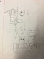
I’m useing a design similar to the picture except I’m useing a mosfet driver and have adjustable duty cycle and frequency on the 555 timer

*The current frequency is 8-10khz and the TVS diode start to heat up with a duty cycle of barely 10% and I also have 10000uF capacitor in parallel with the main dc power supply
 

Attachments

ebp

Joined Feb 8, 2018
2,332
What is the output connected to? Are you sure the phasing of the windings is correct?
If there is no place for the energy stored in the inductor during the ON time to go in the output winding it will "find" some place to go. It sounds like all of it is being dissipated in the TVS diodes and the FET.

Another possibility is that the inductor is not wound well and the leakage inductance is very high, though this seems less likely.

Your switching frequency is very low. Unless there is sufficient inductance in the primary, you may be saturating the magnetic core which makes the primary winding look like just a piece of wire, leading to very high current in the FET. The FET heating and the TVS heating may be due to two different things.

Please post a schematic of the circuit as-built (hand drawn & photographed OK, as long as we can read it clearly; OK to leave out the 555 parts). A photo of the transformer would also be helpful.
 

Thread Starter

Joaquin Valdez 1

Joined Apr 11, 2018
7
I have posted a pic of the schematic I’m using as well as pic of my set up and the transformers I believe I have around 10 turn on the transformer. I increased the frequency to 100-120khz depending on the duty cycle this did little to protect the TVS diode and pop another one I also tried to change The polarity of my connection to the transformer the arc were a lot smaller give me the idea that I had the connection right in the first place. I would also like to know I how would implement a shockky diode instead of the TVS diode as I have never used a schokky diode in this way.
 

Attachments

crutschow

Joined Mar 14, 2008
34,464
A Schottky diode won't work, as it will short the flyback output.

You likely are saturating the transformer core, allowing the current to go very high.
Keep the duty-cycle below the point that things start to overheat and use a higher frequency.
A small capacitor across the transistor from drain to source (say 100-500pF or so) may help.

What is the voltage rating of the TVS and the MOSFET?
 

Thread Starter

Joaquin Valdez 1

Joined Apr 11, 2018
7
A Schottky diode won't work, as it will short the flyback output.

You likely are saturating the transformer core, allowing the current to go very high.
Keep the duty-cycle below the point that things start to overheat and use a higher frequency.
A small capacitor across the transistor from drain to source (say 100-500pF or so) may help.

What is the voltage rating of the TVS and the MOSFET?
I module I’m useing is actually a IGBT and can handle 600v 100amp and the TVS diode is rate for spikes over 400v
 
Top