Facebook
 Google
 GitHub
 Linkedin
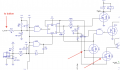
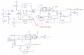
Hello. I restored a driver circuit for the laser diode using driver's PCB and Diptrace. Laser is Thorlabs S1FC635. I have some questions about circuit. I attached some pictures of this circuit.
1)I would like to understand role of the U2.3. "U2.3In-" is signal from drain of Q2.2. When I press "Enable" button on front panel of laser - laser is on and Q2.2 close. So it's some positive voltage on drain. When I increase power of laser(I see actual power (mW) on indicator in front panel), voltage on drain decrease(power of 1mW -> 3.665V on drain, 0mW -> 4.2V on drain). I don't understand what's going on. So I understand that U2.3 is inverting ampilifier, I try to calculate output voltage on U2.3, but in point of "virtual ground" of op-amp is some voltage(not 0V) because there is zener diode in feedback of op-amp, so I don't understand how to calculate VOUT of U2.3.
P.S. maybe Q2.2. performs the function of slow start (standard in good laser drivers)
2)Why two signals (from U1.4 output and from U2.3 output) connected together without resistors? Are their output voltages is summed up? How to calculate voltage in point of connection of two outputs op-amps?
3)What role of optocoupler U5? I think it use for disable of gain in U2.4. But I want to know resistance of emmiter-collector when optocoupler is opened or how to calculate gain with using optocoupler in feedback.
That's all. I will be glad to any help. Thanks in advance
Attachments
-
 49.6 KB Views: 43
 -
 28.2 KB Views: 45