Take out that 22 ohm resistor so the current goes down to 250ma, as in the original design.
There is more to discuss but the idea that you're working with what you have makes it a short list.
A MOSFET would work for Q2 and Q3 if you had the right kind.
Q2 could disappear if you were willing to waste 10 to 30 ma through R2.
That drive current would be less if you had a transistor with better gain.
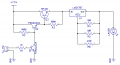
your LM317 is wired incorrectly ,the resistors should be in the output and the adjust should be connected to the load side of the resistors,BUT why so many resistors ,why not just use a 5Ω.
Actually on my test PCB I have the LASER connected to ADJ, but I made a mistake when I made the schematic I will update the schematic when I get home.
I put the 22 ohm resistor because the laser a was a bit brighter I took it off now...
I did not put a 5 ohm resistor because I only have 5 ohm 1/4w, and it was getting hot. I used 2, 10 ohm 1/4w resistors, and now the resistors get warm, so it's better now...
I still don't know how to use MOSFETs yet... can you please modify my schematic to work with a MOSFET?
 Facebook
 Google
 GitHub
 Linkedin
 I will update the schematic when I get home.


