TTL(3.3) to TTL(5.0) via RS485, Is it possible?

Thread Starter

mariosergio

Joined Feb 23, 2018
23
Hello everyone,

It´s my first time in this forum, so please tell me if I´m doing something wrong.

The problem I´m facing is to implement the comunication of a raspberry pi and a PIC MCU that will be about 50m apart.
The serial port in Raspberry uses TTL at 3.3v, while the serial in the MCU uses TTL at 5.0v.

Right now I can use the serial port in my computer to comunicate to any then (individualy) using the MAX3232 IC. The baudRate is 4800.

The protocol I´m using is of my own, it's basicaly a small string that starts with the sender, is folowed by the destinator and then the command.
Something like [BSETO042TON] meaning that BSE(base) is sending a message to 042 telling to TON (turn on). In my work-bench evereyhing work's fine.

The question is how to use the same protocol but in a longer distance?

From what I´m reading RS-485 is the way to go, but how can I implement it?

Thank you verry much for taking the time to help me.

Kind regards
 

MrChips

Joined Oct 2, 2009
35,275
RS-485 should work fine. Power the RS-485 transceivers at 5V at both ends.
At the rPi end, DI pin can accept 3V input. For RO pin, you can attenuate the output with a voltage divider.
 

MaxHeadRoom

Joined Jul 18, 2013
30,871
What do you mean by 'longer distance' RS232 distance can be increased by slowing the baud rate,
For RS485 check out the MAXIM IC's.
Like RS232, RS485 is not a protocol but a TX/RX level.
Max.
 

ebp

Joined Feb 8, 2018
2,332
There are RS485 transceivers that will operate on either 3.3 V or 5 V.

RS-485 is intended for applications where a single pair is used for both transmit and receive (half duplex) and/or where multiple drivers and receivers share a bus. As long as you aren't going to talk to some other RS-485 device you can configure things to suit yourself. It may be more convenient for you to use one pair for each direction (full duplex link). This can be helpful because the sending device doesn't have to stick its fingers in its ears so as not to hear itself talk and there are no issues with line turn-around. Any of the PICs I've used are a bit of a pain for line-turnaround for half duplex. The UARTs are buffered, so there is a holding register and a transmit register. They will set a flag and/or generate an interrupt when the holding register is free to accept another character. This means the flag will be asserted long before transmission of the character in the transmit register is finished, so you have to mess around with timers or other methods to be sure you don't switch the transceiver from transmit to receive too soon and put most of the character in the bit bucket (actually, if the PIC listens to itself, you can generate a flag or interrupt when the char you just sent has been received locally, and use that for line turn-around if the transmit buffer register is empty) If you use a full-duplex configuration with a pair for each direction, this issue goes away. The Pi probably will manage things better in terms of when flags are raised or interrupts generated. Unfortunately, there are not a lot of RS-485 transceivers with the transmitter output and receiver input pinned out separately. I think either Micrel or Maxim has one or two. The problem is that the package needs 10 pins. There may be some RS-422 transmitter-receiver chips that don't have enable pins.

"Ethernet cable" is convenient for RS-422 & RS-485. At your bit rate and distance you can probably get away without terminating the lines, which saves some power. Don't forget you need a common between the two ends. It may come via the power line ground, but if the ends don't connect to earth ground you'll need a ground conductor in your connecting cable. Since the most you'll need is two pairs for signal, you'll have two left over for ground in ethernet cable.
 

ebp

Joined Feb 8, 2018
2,332
Just re-read your original post and it sounds like you may be planning to have several talkers and listeners on a bus, which makes RS-485 a perfect choice. This arrangement is often called "multidrop". If there is a system master that gives each talker permission to talk, it can still be convenient to use two pairs so the talkers only have to listen to the master and not all the other talkers.
 

Thread Starter

mariosergio

Joined Feb 23, 2018
23
Hi, thanks for the reply!

The conversor I´m thinking to use is the MAX485, mounted like the picture bellow, (they are cheap and easy to find here) The cable will be an ethernet cable CAT6 (I can´t change the cable anymore) and the baud rate can be decresed since very litle information is being transmited.

I´m not going to talk to other devices, rather then the ones I have programed myself. I´m not sure about switching to full-duplex, because I allready wrote the program for the PIC, and it´s working fine, and because very little information is going to be transmeted every once in a while. Should I really consider switch to full-duplex?

If I go with half-duplex, I just conect the conversor ignoring the RE and DE pins? And can I also forget about all the explanation I read about RS-485 having masters and slaves and holding only 32 devices? If I´m using m own protocol I can connect how many devices I want right?

And by the way, the whole thing is for home automation.

Max, MrChips, and ebp, thanks again for the help!


Thread Starter

mariosergio

Joined Feb 23, 2018
23
ebp, I just read your last message..

Yes, using the model I have, everyone will be listening to everyone. When they shold be talking only whith the master(raspberry pi).

My problem in changing to full-duplex and use this "multidrop" is that I´m afraid of having to change too much in the code..
 

ebp

Joined Feb 8, 2018
2,332
That transceiver has the RS-485-side driver and receiver pins connected internally, so you have no choice but to use half duplex unless you use two transceivers - one for doing transmit only and another for receive only. I think you have half and full duplex backwards. Full duplex means that you can transmit in both directions on the transmission medium or channel at the same time. Half duplex means you can only transmit in one direction at a time. If you used two pairs, each would be half-duplex (actually "simplex") but the overall channel (your cable) would be full duplex. RS-232 is full duplex - there is a separate data line going each way.

Again, you have be careful about when you disable drivers so you don't lose part of the character (last character in a sequence is the one that could be lost) that is being transmitted. The easiest method is to use a timer. Put the last character in the UART buffer and after you get the transmit buffer empty flag or interrupt (this is on the PIC), wait for one full character time including the stop bit before disabling the transmitter. The Pi may have a much larger buffer like a PC does - you can put many characters into a FIFO buffer all at once. If there is no flag to say "character transmission complete" or if you don't keep careful count of how many of those you get, you may either cut of part of your message or wait longer than you need to disable the transmitter. If the PIC-based device could enables its transmitter before the Pi has disabled its, then you get a conflict on the bus and data will be corrupted. I suspect you can find lots of things on the web that talk about this in detail and give code examples.

The MAX485 requires a 5 V power supply, so you will need to protect the Pi input from excessive voltage (unless the input is "5 volt tolerant"). You can probably do the job with just a resistor between the MAX485 output and the Pi input to limit current and let the protection diodes in the Pi take care of limiting the voltage. A 10k resistor would limit the current to (5-3.3)/10 000 = 0.17 mA, which should be completely safe, but you should check the Pi specs to be certain.

Because the MAX485 has high slew rate, you may need to terminate the line at each end, but it may be OK without termination. Read the applications notes published by Maxim and others
 

Thread Starter

mariosergio

Joined Feb 23, 2018
23
Hello everyone,

First of all, thanks for the help!

Ebp, you are right, I´m didn´t get half-duplex and full-duplex. After reading your message I understand that if I don´t wanna make changes in my code them I must use Full-duplex and not the other way around. Since I had a hard time implementing the protocol in the PIC using serial(full duplex) I wonder how long it will take me to re-writ it to half-duplex..
So I must decide betwin re-write the code, with is hard, or to use 2 tranceivers, with uses too much space in the little box..

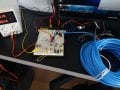
To avoid those questions today I decided to run an experiment to see how far can I go with serial rs-232. I bought 30m of ethernet CAT6 (why so expensive?) and connected it to my system. It was abble to comunicate perfectly at a baud rate of 3500, with is the maximum that my PIC can handle even if connected directly!. I then connected the pairs of the cable to each other to make the signal go throu the cable multiple times. By doing that the signal had to travel 120m and it is still working fine!

So now I´m seriously considering using the RS-232, even if I have to lower the baud-rate to half of that. You guys see any problem?

I apreciate you help ebp, it´s now clear to me the options that I have, and the fact that I need to do more research in how the RS-485 works in a physical way.

below is a picture of the experiment...
Thanks

20180224_142709.jpg
 

MrChips

Joined Oct 2, 2009
35,275
I see no problem using RS-485 and half-duplex. You will only need one RS-485 transceiver with each device. I would bias and terminate the RS-485 lines as per standard practice.

You do not have to rewrite the protocol. As Max says, the RS-485 is the hardware layer, not the protocol. The protocol is primarily how you package the message and that is entirely up to you to choose.

The only issue is how to determine when the PIC has completely finished transmitting the last byte, as ebp as indicated. There are a number of solutions which we can go into later.
 

MrChips

Joined Oct 2, 2009
35,275
RS-485 is more robust than RS-232 because it uses differential signalling. There are two data lines, A and B, and one is always the complement of the other. RS-485 is good to 1200m at 76800 baud.

What Microchip PIC are you using and at what xtal frequency?
Most PICs UART can easily run at 115200 baud.
 

MaxHeadRoom

Joined Jul 18, 2013
30,871
I decided to run an experiment to see how far can I go with serial rs-232. I bought 30m of ethernet CAT6 (why so expensive?) and connected it to my system. It was abble to comunicate perfectly at a baud rate of 3500, with is the maximum that my PIC can handle even if connected directly!. I then connected the pairs of the cable to each other to make the signal go throu the cable multiple times. By doing that the signal had to travel 120m and it is still working fine!

So now I´m seriously considering using the RS-232, even if I have to lower the baud-rate to half of that. You guys see any problem?
I have used RS232 in Noisy Industrial environments for around the same distance with no problems, usually 4800 baud tops.
Max.
 

MrChips

Joined Oct 2, 2009
35,275
BTW, I use a very simple protocol that is based on MODBUS.
A message such as your [BSETO042TON] would be transmitted as

$AON

plus checksum and CR terminator, total of 7 bytes transmitted.

If you would like to see the full specs of the protocol I can post it here.
 

ebp

Joined Feb 8, 2018
2,332
RS-232 can work very well over long distances if the bit rate isn't too high and there isn't a problem with "ground loops".

When originally conceived, RS-232 was intended to connect "data terminal equipment - DTE) to "data communication equipment - DCE." DTE was often just that - a user terminal of some sort. DCE often meant a modem. All of that equipment was normally powered from AC mains and for safety reasons the exposed metal bits were connected to earth ground via the power cord. Signal common was normally connected to earth ground, too. Some things will put significant current into the ground connections, which can cause a voltage difference between the grounds for two pieces of equipment that are far apart. RS-232 has a signal common connection in the cable. The two separate but connected ground paths form a "ground loop." If the earth grounds are not both at the same voltage, this can lead to unwanted current flowing in the signal common, which can degrade the actual signals. In some places it is perfectly legal to run hundreds of amps of welder return current through the structure of a building (I was a bit aghast when I first learned that) Not a good place for RS-232.

RS-232 has quite good noise immunity. Any voltage on a signal line between -3V and +3V is supposed to be treated as undefined. This means there can be a lot of noise on the signal without causing problems. It also means that the rise and fall of the signal can be quite slow without causing difficulty.

When something doesn't have an earth ground connection, the ground loop problem goes away. If the bit rate is low you can actually add extra capacitance from the signal connections to circuit common to filter noise. For lots of things, especially at low bit rates, RS-232 would probably be quite reliable at 200 metres. But it is risky. RS-422, which actually defines the signal characteristics used in RS-485, uses differential techniques that improve reliability at much higher speeds and for long connections.

You can put multiple RS-232 receivers on a common connection, within reason, though this was never the intent. You cannot put multiple RS-232 transmitters on a common connection without adding circuitry. I know of no RS-232 driver that can be set to high-impedance ("tri-state") output.
 

ebp

Joined Feb 8, 2018
2,332
The MAX13432 is a very good part for low data rate full-duplex 422, with failsafe operation for open or shorted line, 3.3V or 5V operation, and slew-rate limiting (often eliminates need for terminated lines). But it is a ten pin package and I doubt if a ready-to-use module can be found.

https://datasheets.maximintegrated.com/en/ds/MAX13430E-MAX13433E.pdf

I haven't checked the price. Maxim has always been very generous to itself with its prices. I've seen lots of similar chips that cost more than lots of microcontrollers.
 

Thread Starter

mariosergio

Joined Feb 23, 2018
23
Hello everyone,

I apreciate the help from you guys, but it seams that my problem is now solved. (at least this one..)

I re-run the experiment with the "120m" cable, this time I unraveled the cable and made it go througt my house trying to get some noise. None I my house equipment was abble to add any changes to the signal, nor my tv, nor the motor in my fan, nor the motor in my fridge. So I decided to use RS-232, and keep the 485 for when I need faster comunication or longer distance.

MrChip, about the protocol, I apreciate you help, but developing the protocol is the "fun" part for me. I defitely gonna add the checksum, it´s very obvious that I need one, but I haven´t thought about it before.

ebp, about the ground loops, thanks for the warning, but it wont be a problem since the devices will not be conected to ground, and the ground network itself is conected to a RCD so I don´t think there will be much current going throught the ground..

Well, I think that covers my original issue.

As about my project, for anyone interested..
It´s a device that receives messages from a raspberry pi and them uses the information to dim 2 different lamps independently.
The device is mounted on a case the size and shape of a circuit breaker case, so it can be mounted as one.
The two lamps are controled using 2 triacs (TIC236D). The PIC is a 16F688 running with a 20K cristal. The speed of the PIC is a problem because it must be fast enought to receives and process the serial signal while still dimming the lamps, and it also must trigger and interruption everytime the voltage changes in the AC line (60Hz over here).

The raspberry pi is running openHab 2, a realy good open sourcer project for home automation.
Right now, the circuit in my protoboard works so I can control the dimming of two lamps using my cellphone with or without wireless network.

I can give more information on the cicuit if someone is interested. Just let me know.

Thanks again for the help! I will be probabily coming back with more questions..
 
Top