TSOP SENSOR MODULE

Thread Starter

Arjun Rajput

Joined Aug 15, 2020
8
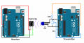
I'm creating a tsop sensor module. When I use different power supply for transmitter and receiver my module works. If I connect both sides with same battery it stops working. There is some ground problem I guess


Please help me out with this
 

jpanhalt

Joined Jan 18, 2008
11,087
My guess is that the power supply is not adequately isolated from the transmitter and receiver. Noise in the receiver could interfere with detection.
 

jpanhalt

Joined Jan 18, 2008
11,087
1) Separate supplies work.
2) Add 0.1 uF, 1.0 uF, and 10 uF capacitors in parallel and as close as practical between the supply lines (VCC) and ground of the Arduino board transmitter 5 V connection, receiver TSOP supply, and receiver board. That's probably overkill.

You do have a common ground. Right?
 

Thread Starter

Arjun Rajput

Joined Aug 15, 2020
8
I'm using both ground and VCC from same battery / Arduino board. I do have a common ground and the receiver led keeps on blinking.


I will try putting capacitors in my supply from battery/Arduino board.
 

sghioto

Joined Dec 31, 2017
5,376
Is the plan to use the same arduino for both transmitter and receiver?
I think from post #4 he means using two separate UNO boards and using a atmega 328p chip on each.
Looking at the schematic of the UNO there should be adequate capacitance in the DC input and regulator circuit already, including a DC blocking diode.
SG
 

Thread Starter

Arjun Rajput

Joined Aug 15, 2020
8
I think from post #4 he means using two separate UNO boards and using a atmega 328p chip on each.
Looking at the schematic of the UNO there should be adequate capacitance in the DC input and regulator circuit already, including a DC blocking diode.
SG
No I want to make a working model on breadboard. So I have to connect everything on a single atmega chip.
 

MisterBill2

Joined Jan 23, 2018
18,167
It may also be that on one of the modules the output is commoned with one side of the supply while on the other module the opposite side is made common with the output. Or the issue may be with the processor board.
AND, for those of us not familiar with every acronym, what is a "TSOP Sensor"?
 

Thread Starter

Arjun Rajput

Joined Aug 15, 2020
8
It may also be that on one of the modules the output is commoned with one side of the supply while on the other module the opposite side is made common with the output. Or the issue may be with the processor board.
AND, for those of us not familiar with every acronym, what is a "TSOP Sensor"?
I have used the pinout of datasheet that came with my sensor pinout for tsop 1738.
 

MisterBill2

Joined Jan 23, 2018
18,167
The specified pinout of any of the elements of the system may include the incompatible connectivity that I mentioned. It would not be a case of incorrect connection, it would be a situation of incompatible hardware designs. I presented the possibility as one possible cause of the problem, not the certain cause.
Another possible cause is that with all three modules powered by the same battery there is a momentary overload that is dropping the voltage available. Checking the voltage with a fast meter may reveal that condition.
And it may also be possible that the physical connections are not adequate. That has been a problem with some setups previously. Some test leads used in some setups are not adequate for the task.
 
Top