Facebook
 Google
 GitHub
 Linkedin
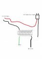
Hi, I'm playing around with trying to make a set of LED xmas lights flash using a Raspberry PI GPIO pin. I've purchased a cheap set of lights from Target. The power supply states: Output 31V 116mA 3.6W. I figured I would just snip the wire about a meter from the output and wire it into a breadboard with a ULN2803 and have the power supply output +ve 31V hooked up to COM, the -ve 31V hooked up to GND. Then hook the LED light side +ve to the +ve 31V from the power supply and the -ve side to O1 of the ULN. I would then connect a GPIO to I1 and use this to flash the lights. See the attached figure 1 for my wiring. This doesn't seem to work. If I look very closely to the LED lights there may be a slight very dim flicker occasionally.
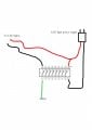
Since this didn't work I wanted to make sure the principle would work, so I wired up a single LED using 5V from the PI as the voltage. See attached figure 2. This seemed to work fine. I can measure a voltage between O1 and COM alternating from 5V to 0V. Whereas on the original circuit there is just a continuous 0V between O1 and COM.
Am I doing something wrong here? Also attached a photo of the power supply, which powers the LED lights fine when directly connected.
Any suggestions would be welcomed.
Regards Paul.
Attachments
-
 59.5 KB Views: 15
 -
 54 KB Views: 14
 -
 290.4 KB Views: 14
") .
.