Facebook
 Google
 GitHub
 Linkedin

schmitt trigger
- Joined Jul 12, 2010
- 2,229
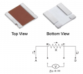
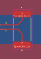
Since these resistors are very low-valued, the connecting wire’s resistance will be a significant percentage of the resistor value. In the schematic, these are A and D. These are called the “force” wires and are the pair of large pads in your photo.
To prevent reading the spurious resistance, a pair of “sense” wires are connected immediately at the resistor’s resistive element. These are labeled B and C and are the pair of small pads. As also stated in the schematic, the meter connected to these pads will have an extremely large impedance, and therefore will not impose a loading on B and C.
To prevent reading the spurious resistance, a pair of “sense” wires are connected immediately at the resistor’s resistive element. These are labeled B and C and are the pair of small pads. As also stated in the schematic, the meter connected to these pads will have an extremely large impedance, and therefore will not impose a loading on B and C.