Trying to keep a scroll saw from ending up in the trash

Thread Starter

bxdobs

Joined May 11, 2014
32
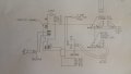
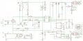
Saw given as is, to a group of individuals that donate their time doing woodworking projects for the community at large and would be a welcome tool. Unfortunately the Speed Control board is not working properly ( the motor runs full speed with absolutely no control ) Reverse engineered the circuit (schematic attached) ... based on bench testing, I suspect U2 has failed ... the SCR's (TXN40) are not shorted which is what I expected would cause the motor go full speed ... U2 has its identification ground off so I am hoping someone might recognize this IC based on the surrounding components. My original thought was this might be some sort of MCU but being that the designer went to a huge amount of trouble just to add a divide by 2 circuit (the motor has a slotted wheel sending pulses back to U2 pin 7) this is more likely a device that can be sourced. Being this is a SCR circuit, the first thought would be that U2 may be some sort of PWM chip.

Thoughts?
 

Attachments

LesJones

Joined Jan 8, 2017
4,511
Are L1, L2 & L3 separate inductors or windings on a pulse transformer. I think this is more likely to be a phase angle control system than PWM. Have you checked that you are getting speed pulses at pin 7 of U2. If there are no pulses on pin 7 then the controller thinks the motor is not up to the set speed so will be trying to increase the power to the motor.

Les.
 

bwilliams60

Joined Nov 18, 2012
1,450
Do you have a picture of the make and model of saw as well as some good pics of the circuit board? I have controller boards taken off variou woodworking equipment and maybe I can match it up?
 

Thread Starter

bxdobs

Joined May 11, 2014
32
Thanks Les,

L1 ,2 and 3 are coils in a "pulse" transformer (no idea how the polls are oriented but each coil measured approx 2 ohms out of circuit) ... I did have a scope hooked to pin 7 but it showed no activity from 0 to 100kHz ... I only have the board at the moment so guesstimated a frequency to inject in to the detector (don't currently know the motor's max RPM or slit count for the detector wheel) ... based on some rough math plus simulations both online and in altium, I figured that the 2 caps and 2 resistors connected to pin 7 should adequately pass signals from 0Hz to 20kHz ... set a sweep generator from 100 to 100k but was unable to detect any signal at pin 7 suggesting either the IC input is dragging down the signal or possibly C4 is open circuit ... next step may be to swap C5 and C4 and or remove the IC from the board.

Most of the online SCR motor control circuits are using 555 timers (pin 7 on a 556 is GND which doesn't match this circuit) ... the old incandescent dimmers which use Triacs basically vary how much of the AC wave is chopped off on both halves of the cycle ... was expecting this circuit should work the same way.

As the "pulse" transformer drives the SCR gates, pin 3 of U2 is most likely the pulse generator signal source ... Note: my bench tests were done prior to generating this schema ... basically the unknown IC appears to have the following key connections:

Pin 2 - U2 V+ (signals and polar cap orientations seem to indicate the boards GND is positive with respect to this IC)
Pin 4 - U2 GND (R1 is a 5W resistor so may actually be providing U2s GND reference ... this pin was measured at -14.5V)
Pins 10 & 11 - input from the external 50k speed control pot
Pin 7 - Motor Speed Sensor Signal divided by 2
Pin 3 - "pulse" transformer driver?
Pin 1 - SCR feedback?
 

Thread Starter

bxdobs

Joined May 11, 2014
32
No pics sorry, this group was donated some remote space which is only accessible at certain times of the week and has been hard, with the weather of late, to get to. The board is 2 x 5" and is stamped with GE HOW CSY ---IIII Corporation Ltd 39782 ... this is off some no name brand Chinese made Scroll Saw ... I have attached a sheet that came with the saw

The 3rd hand story of this saw was the original owner attempted to change the Lighting Arrangement when the saw stopped working ... the 1/4" wide board trace from N (Pin3 on the attached file) to S1 was completely blown off by some apparent short circuit ... if the saw was running at the time of the short circuit the board's circuitry likely received a huge spike which could explain the cause of this failure.
 

Attachments

Last edited:

LesJones

Joined Jan 8, 2017
4,511
If there are no pulses on pin 7 of IC2 then it thinks the motor is stopped. Photo interrupter OK1 is going to have a slotted disk interrupting the light (Which is probably infra red so you won't be able to see it.) Disconnect the wires to the motor. Monitor the voltage between pins 4 & 5 of OK1 Note the voltage when the disk is blocking the light path and when it is not blocking the light path. One should be higher than about 2 volts and one should be less than about 1 volt. It is possible that the optical path is blocked with wood dust so try clearing this with compressed air. Report the results.

Les.
 

Thread Starter

bxdobs

Joined May 11, 2014
32
Les,

All I have is the board at the moment so was injecting a signal to pin 11 of U1 from a signal generator ... I had tested the output from the sensor before the board was removed and it was changing state ... I swapped C5 and C4 as a test this morning but thinking because the motor is not in circuit the SCRs may not be firing the way they would under load ... assuming this motor has brushes there would be inductive kick back that may be required for the circuit to work properly.
 

Thread Starter

bxdobs

Joined May 11, 2014
32
All the members of this group are retired and basically donate their time to do projects for other people in need ... as such, there is really no budget to replace/purchase parts/tools ... they completely rely on donations all project materials are either donated or provided. So yes, a new speed controller would most likely work but was hoping for the $2 fix. I was just expecting to have to replace the SCRs. I will hopefully obtain the motor weather permitting and run some real life tests.
 

MaxHeadRoom

Joined Jul 18, 2013
30,557
. assuming this motor has brushes there would be inductive kick back that may be required for the circuit to work properly.
Most likely that it does have brushes, it would be a Universal (series) motor, this one appears to be running on DC, hence the bridge.
With no feed back they operate in a runaway condition, speed then is dependent on load.
Max.
 

LesJones

Joined Jan 8, 2017
4,511
Was the signal that you injected into IC1 pin 11 of a suitable voltage swing to drive IC1 input ? (Square wave low level zero and high level 3.3 volts.) Did you check that you had a waveform on pin 13 of IC1 that was half the frequency of the signal generator ?. You should be able to test the board on the bench using a mains voltage incandescent lamp (About 100 W) as a load in place of the motor. You will need to inject the signal from the signal generator. as you increase the frequency the lamp should dim when the frequency is what you expect to get from the speed sensor when the motor is running at the set speed.

Les.
 

MaxHeadRoom

Joined Jul 18, 2013
30,557
I would expect to see a AC phase control with that circuit, I believe there maybe some error in the mains input (transformer?) and it is most likely sync'ed to the 50/60c as phase angle control, also J1-2 I assume is a neutral?
Earth ground symbols have been used throughout which causes some confusion.
Max.
 

Thread Starter

bxdobs

Joined May 11, 2014
32
Thank-you one and all for your time ... finally received the motor and was able to find and repair the fault.

Not certain why my signal generator wasn't triggering the control circuit properly (it was set to 3.3 V and referenced to the 3.3V circuit GND) ... regardless ... when I connected the motor and it's sensor, there was absolutely no signal coming from the sensor. Pulled out the sensor and it still passed all standard tests (This was one of the first things I had checked and ruled out onsite when originally testing the Saw ... because the cable connector is too small to probe with my meter probes, I had tested the sensor directly at it's 4 I/O pins) ... even changed the supply voltage to 5V to increase the sensor driver current (removed the zener and zener series 1k2 resistor and plugged in a LM340T5) with no change to operations ... on closer inspection, found there was actually a hairline crack/fracture in the sensor's cable interface board (the power trace was fractured where the solder resist met the pad) which was disrupting power to the Led ... after repairing the sensor connection and putting back the Zener (3.3V) the motor started behaving properly by following the speed pot. (suspecting this fracture was there all along and had just been intermittently making connection)

Notes:
1) the motor is a Delta 40-650C variable speed, 115V, 60Hz, CS/M 300-2000 (presuming CS/M means RPM rotations per minute) the sensor wheel has 50 slits, so expecting the frequency from the sensor to be in the 15k to 100kHz range ... and yes this motor has brushes

2) the sensor (resembles digikey OPV840L 365-1101-ND) is protected by a motor end cap which keeps out white light plus should ensure most sawdust is kept from fouling up the IR path.

3) Max, I referenced N (neutral) mains as GND because the 3.3V circuit references this as it's GND ... yes, this is confusing because for U2, this GND reference is actually V+ ... measuring from pin 2 to pin 3 with GND as a reference, Pin 3 is negative with respect to Pin 2. ... I confirmed with both a multi-meter and scope that all of the GND points on the schematic are indeed connected together to the N terminal of the AC line. I have a special BREAKERED MAINS ISOLATION TRANSFORMER coupled with a 120VAC VARIABLE TRANSFORMER (VARIAC) ... this allows me to attach my scope and vary AC input voltages to AC devices (DUTs devices under test) without the danger of accidentally shorting out either the mains or circuits under test with my scope probe leads.

4) The original schema uploaded has a multitude of errors due to poor editing followed with not re-validating the actual net list ... using Eagle, I was having to delete connections to move around components (the goal to make the circuit easier to read) ... in the process, I made some incorrect re-connections ... after verifying the net list was correct, it was clear the edited version of the circuit was somewhat out to lunch specifically with some key areas surrounding U2 ... a corrected version of the schema is attached

5) IMHO it would still be advantageous, for future reference, to know what U2 really is (14 Pins) ... the power pin profile/scheme with Pin 2 as V+ and Pin 3 as V- seems to be a very uncommon (unique), which I expected would make it simpler to identify this chip ... most PWM chips I found (digikey/mouser) have 16 pins ... didn't find any phase chips ... most Motor control chips appear to have heat sink pins and numerous NC (no connection) pins ... Micros have various power pin configurations: 1:14, 14:7, 11:4 ... op-amps typically follow: 14:7, 11:4 ... so not sure what this chip could be. If this was some proprietary chip (proprietary is costly for small production numbers), why bother grinding off the chip info, if this was a micro, most micros are code protected, so without the code, knowing the micro still limits ones ability to repair a board ... logic chips follow 14:7 power profiles, in a 14 pin package 3 pin oriented discrete arrays like transistors would end up with at least 2 NC, PLA's might fit this chip's profile but again not everyone has the ability to program a PLA ... The key pins for U2 based on the corrected schema are:

Pin 02 - V+ (appears to be the chip's VCC pin)
Pin 03 - V- (appears to be the chip's GND pin)
Pin 04 - O/P SCR Gate Pulse Driver
Pin 07 - I/P (50 * 300 / 2) - (50 * 2000 / 2) Hz (based on divide by 2 circuit, 50 slit sensor wheel and Motor CS/M 300-2000 specification)
Pin 10 - I/P External 50k Speed Pot Offset Voltage
Pin 13 - O/P External 50k Speed Pot Reference Voltage ... expected there to be an external reference for this pot ... the chip must be supplying this reference internally as there is no other power reference connections to this net
Pin 14 - I/P 60Hz (would be useful for determining Zero Cross Points)
the remaining PIN functionality on this chip isn't clear without knowing what the chip is doing internally

In closing, all searches surrounding this Saw and Motor indicate this particular controller is no longer available from any source. While it is understandable that vendors go out of their way to keep products a mystery for numerous reasons AND/OR manufacture virtually non-repairable products to hopefully promote purchasing newer products from them, perhaps we should be lobbying governments to force vendors to disclose discontinued product literature to those of us who dislike being part of the ever growing e-trash saga.

My thoughts are there should be a way to register as a NON Manufacturing Repair Service with the ability to access discontinued product literature. Basically any vendor wanting to sell a product containing Electronics would need to submit ALL manufacturing details to a repository (hmm like UL) and these details would be available to registered Service Depots once a product is either deemed discontinued or a vendor has closed shop.
 

Attachments

Top