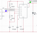
Trying to configure a 555 astable timer for a bike alarm but its not working!!!!

Thread Starter

SyedAdilBukhari

Joined Mar 26, 2024
5
Hey y'all..
so basically I am trying to build this anti-theft alarm system and I am using a 555 astable timer to make a LED light up intermittently. However, once it rises to HIGH voltage it stays at HIGH and it does not oscillate. What should i do? Using Multisim Live as I am on MacOS :( . CaScreenshot 2024-03-26 at 8.42.46 PM.png
All values are correct to my own specifications. it just does not want to oscillate.
 

crutschow

Joined Mar 14, 2008
34,912
No surprise it doesn't oscillate for either logic output of the U3 latch.
That connection to the latch will kill the 555 operation as its output is basically a short to either ground or V+.

If you want U3 to inhibit the 555 then connect it to the 555 RST pin.
A low on that pin shuts off the 555.
 

dl324

Joined Mar 30, 2015
17,222
Welcome to AAC!

You haven't told us about how the flip flop is being used.
  1. What does Q# do before and after you want the timer to oscillate?
  2. What is the purpose of having the flip flop connected to trigger/threshold? If you want the timer to oscillate, you need to let the capacitor charge and discharge through R2 and R3.
  3. The high side of R2 should be connected to VCC, not ground. What does the switch do?
 

Thread Starter

SyedAdilBukhari

Joined Mar 26, 2024
5
No surprise it doesn't oscillate for either logic output of the U3 latch.
That connection to the latch will kill the 555 operation as its output is basically a short to either ground or V+.

If you want U3 to inhibit the 555 then connect it to the 555 RST pin.
A low on that pin shuts off the 555.
Hi thanks for the reply. The flip-flop is meant to initiate the 555 astable timer. Q# is meant to be LOW at first and in order for the timer to oscillate Q# should be HIGH.
LOL i didn't even notice R2 being connected to ground, silly me! these late nights have been getting to me. Thanks for helping
 

crutschow

Joined Mar 14, 2008
34,912
Ive managed to get it to oscillate through using output from Q as the main power and threshold point for the 555 timer.
]That circuit requires U3 to provide the power to the 555 which is not a good way to control the 555.
Why not connect it just to the RST terminal, as suggested?
 
Top