Troubleshooting a simple audio amplifer that's gone DC

Thread Starter

stdave

Joined Jun 25, 2017
6
This is my first post to this billboard, so if I have done some thing out of order, or need redirection please let me know. I have done some troubleshooting in the past but am not a veteran tech, and would appreciate some direction.

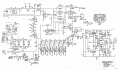
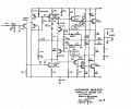
I have a simple audio amplifer - all transistors, an older design, that all of a sudden went DC on me. There are 13 transistors in this circuit, four of them are output transistors that are heat-sink mounted. In my experience often audio amplifiers that go DC (DC on the speaker circuit) have shorted output transistors. So that was the first thing I checked - all of those transistors are fine - I actually pulled those to test. This amplifer has a +44V, 0V, -44V power supply and the speaker circuit is outputing +44V. I have been testing many of the transistors for shorts (mostly in-circuit tests) and have come up with nothing that looks suspicious. I have done the same with the diodes and the capacitors, also with no problems noted. So now I am at a stalemate. In my experience resistors, usually blow with a big stink and a lot of fanfare, and I don't see any of that. The ones I've tested are fine.

I have attached a schematic of the amplifier, the input is on the left, the speaker output on the right. The power transistors are the four MJ15015 on the right. Any guidance on the best course of action to follow in terms of voltages to test at certain points, or expected oscilloscope waveforms at certain stages would be great.
 

Attachments

Thread Starter

stdave

Joined Jun 25, 2017
6
Yes - actually this product also has a mixer built in as a prior stage, which works fine, off the same power supply - the output of that mixer goes into the input of the amplifer in question.
 

KJ6EAD

Joined Apr 30, 2011
1,581
That's an ambiguous answer since I don't know what supply voltage is used in the mixer. Is the ±44V stable in the power amplifier section?

If the entire +44V is appearing on the output, you already know the likely culprits and have been testing for them. You just need to continue, perhaps start lifting transistor and capacitor legs that could short to the rail.
 

MrChips

Joined Oct 2, 2009
30,795
Remove the four output power transistors.
Power up the circuit and measure the voltages with respect to ground at the legs of all the transistors.
Post your measured voltages here.
 

Thread Starter

stdave

Joined Jun 25, 2017
6
Well, that did not go as planned. While reading voltages on the transistors I shorted, got a puff of smoke from a resistor (which didn't blow), but something must have blown, because now I have DC on the output - but it's negative -47V instead of positive. Anyhow I took the reading that you suggested, after my mishap. So, for what it's worth;

On the MPS8598 transistors close together,
top E+46.9 B+46.3 C-46
left E-46.2 B-39.2 C-46.4
right E-46.4 B-37.6 C-46.5

the 2n6556 = E+46.2 B+46 C-44.8
the 2n6553 = E-46.6 B-46.2 C-46.7


Voltages of interest:
Input circuit transistors MPS8598; call it top, left and right) BCE to ground (9 Voltages)
2n6556 (E) to 2n6553 (E)
 

Thread Starter

stdave

Joined Jun 25, 2017
6
That's an ambiguous answer since I don't know what supply voltage is used in the mixer. Is the ±44V stable in the power amplifier section?

If the entire +44V is appearing on the output, you already know the likely culprits and have been testing for them. You just need to continue, perhaps start lifting transistor and capacitor legs that could short to the rail.
Regarding the power rails - it's a very simple power supply - just a transformer with a center tap and a diode bridge and some capacitors. It appears stable - it's got the 0V, 46V+ and 46-, the voltages do not jump around even with current draw.
Regarding your comment about continuing, by lifting legs that could be shorting - my concern was that the positive +46V that appears on the speaker line could also be there because of a negative part of the circuit blown -open-, thereby removing one side of an amplifier positive/negative balance to 0V on the speaker line under normal circumstances. I am somewhat lost with respect to what can be removed from the circuit and then somehow determine the meaning of the result of doing so - my only thought on that is that originally on noticing the problem, the 15" speaker, when connected actually jumped out an inch, and wanted to stay there. That's no trickle voltage on the speaker line. So there, I can see your idea of lift legs as useful. What ever path is allowing that kind of current to flow to speaker I'm guess is where the problem lays, and it would make sense to experiment to find that.
 
Check the two 100 ohm resistors at the top and bottom of the schematic. The two 2n65** forms a temperature compensated bias regulator. That's not working.

The BC319 and the MPS form a limiter.

What we called the top is basically a current source for the differential amplifier.
 

Dodgydave

Joined Jun 22, 2012
11,301
Well, that did not go as planned. While reading voltages on the transistors I shorted, got a puff of smoke from a resistor (which didn't blow), but something must have blown, because now I have DC on the output - but it's negative -47V instead of positive. Anyhow I took the reading that you suggested, after my mishap. So, for what it's worth;

On the MPS8598 transistors close together,
top E+46.9 B+46.3 C-46
left E-46.2 B-39.2 C-46.4
right E-46.4 B-37.6 C-46.5

the 2n6556 = E+46.2 B+46 C-44.8
the 2n6553 = E-46.6 B-46.2 C-46.7
Which resistor was burned, and which transistor were you measuring at the time?
 
Top