Facebook
 Google
 GitHub
 Linkedin
Well not exactly! Very new to electronics cct design, and I have this problem......Any advice would be very welcome.
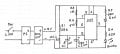
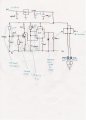
I'm after the following solution, a toggled switch when selected, will operate a green LED, then after a time delay of 10 - 15 minutes extinguish, simultaneously operating a red LED to remain on until the toggled switch is selected off.
I selected a 555 timer as the reviews appeared quite robust and relatively easy to operate for beginner-ish level. I thought potentially, I could operate the 555 in a monostable configuration. With the output driving a relay, this would switch over the earth paths when energised, ensuring one LED would always remain illuminated. Satisfaction of my relay solution then turned to dismay........
The problem!!!
The toggled switch must supply the power for the circuit and also be the trigger for the timer. All the other circuits I have seen have the circuit powered with a supply, then triggered from a push button switch either high or low.
Is this possible? Or am I chasing my tail with this philosophy?
I have attached a circuit diagram of my proposed design, which has taken about a week of research! But im starting to lose confidence in my abilities now.
Further info on the stipulations for the proposed circuit;
The 24VDC supply is attained through a toggled switch (not push button type), I've incorporated a 7812 Voltage regulator to step the voltage down to a more friendly 12VDC.
Any comments or feedback would be greatly appreciated. Many thanks for your time.
Attachments
-
 4.8 MB Views: 211