Trigger Schmitt using LM393N

Thread Starter

analogtape

Joined Jan 9, 2022
4
Hello;

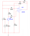
I've found this schematic which implements a trigger Schmitt using a LM393N. I'd like to know the explanation of the circuit, why are the resistors chosen and how to calculate their values. Thank you in advance.

Find the files attached.
 

Attachments

dl324

Joined Mar 30, 2015
16,922
Here you have it.
Where did you find that circuit? The way it's drawn obscures function, resistor values are odd, and Q2 is being abused.

It's the 3 resistor Schmitt comparator variant.

From the 1994 National Semiconductor Linear Applications Handbook:
1641745359122.png
Resistor value calculations are in the attached PDF.
 

Attachments

Thread Starter

analogtape

Joined Jan 9, 2022
4
Where did you find that circuit? The way it's drawn obscures function, resistor values are odd, and Q2 is being abused.

It's the 3 resistor Schmitt comparator variant.

From the 1994 National Semiconductor Linear Applications Handbook:
View attachment 257221
Resistor value calculations are in the attached PDF.
Thank you! A friend of mine sent it to me, and asked me to check it out.
 

Papabravo

Joined Feb 24, 2006
21,225
The output of the Schmitt Trigger determines two different thresholds. When the output is at Vcc, the threshold is set at the lower trip point, and when the the output is at GROUND the threshold is set at the upper trip point. The rest is just the relentless application of KCL.
 

AnalogKid

Joined Aug 1, 2013
11,044
That is a bizarre set of resistor values, and none of the ones that matter (R1, R2, R3) are standard values. The LM393 input offset and bias errors far outweigh the precision of a 4-digit resistor value.

Also - Because R4 is so close to the value or R3, it affects *almost all* of the hysteresis calculations. In the PDF above, this is bypassed with an assumption stated in equation 5. Your values for all of R1 - R4 are so close together that most of the math in the PDF does not apply directly to your circuit; almost every equation needs an additional Rpullup term. In your circuit, R4 appears in series with R3 when the U3B output is high, but not when it is low. This is a messy complication, but not complex.

ak
 

Thread Starter

analogtape

Joined Jan 9, 2022
4
Could you please show me the calculations to obtain the R values in this circuit and explain me how to do it? Thank you.
 

AnalogKid

Joined Aug 1, 2013
11,044
The calculations are on pages 2 and 3 of the PDF. Page 3 has a design example based on figure 7, which is the one you want for your circuit. To be more accurate, equations 1, 3, 6, and 8 need to have the Rpull-up term added in series with R3. this is PDF R3, not your schematic R3.

ak
 
Top