Triac light dimmer controlled with DC voltage

Thread Starter

KevinHowJones

Joined Jun 19, 2022
30
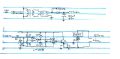
Whatever you do, you will need a zero-crossing detector on the input, and an optically coupled output circuit.
Yeah, I'm pretty clear on that now.

Wondering, the MOC3041 opticoupler has a zero-crossing detector. What does that accomplish in the coupling stage? I can see the need for it in the preceding stages so to know when to generate the pulse, but I don't get what it is for in the opticoupler stage. I'm trying to understand that from the datasheet but I'm not seeing it.

Or maybe I'm just not understanding the circuit altogether?
 

Ian0

Joined Aug 7, 2020
13,132
Wondering, the MOC3041 opticoupler has a zero-crossing detector. What does that accomplish in the coupling stage?
That ruins it completely. If you use a zero-crossing opto-triac, you can only get complete half-cycles at the output. You need a random-phase optotriac (MOC3021) so that it can trigger at any point in the cycle.
 

Thread Starter

KevinHowJones

Joined Jun 19, 2022
30
That ruins it completely. If you use a zero-crossing opto-triac, you can only get complete half-cycles at the output. You need a random-phase optotriac (MOC3021) so that it can trigger at any point in the cycle.
Phew, okay, good, that makes more sense. I must have have been mixing your circuit up with another one I saw using a 3041, or maybe I just accidentally typed 3041 instead of 3021 when looking it up.
 

Ian0

Joined Aug 7, 2020
13,132
Haven't designed it yet. The point is, I want to control the phase angle of a triac using a voltage input. Where the voltage comes from is inconsequential, no?
If you are controlling a heater, and the object to be heated has a large thermal mass, then you would be better off with a proportional control circuit, not a phase control circuit, so that the output is always complete mains cycles. It eliminates the interference from the triac circuit.
 

Thread Starter

KevinHowJones

Joined Jun 19, 2022
30
If you are controlling a heater, and the object to be heated has a large thermal mass, then you would be better off with a proportional control circuit, not a phase control circuit, so that the output is always complete mains cycles. It eliminates the interference from the triac circuit.
Not sure I follow. I am making a proportional control circuit, and using phase control to modulate the heater. The modulation is proportional to the change in temp at the sensor, within the proportional band.
 

LowQCab

Joined Nov 6, 2012
5,101
Knowing the mass of the object being heated,
and the estimated amount of Average-Power that will be required,
and the amount of precision in Temperature-Control that You require,
all are very important factors in designing this Controller.

You're starting in the middle, instead of at the beginning.

Start with defining exactly what it is that You expect your device to accomplish,
and all of the surrounding details of what You have to work with.
.
.
.
 

Ian0

Joined Aug 7, 2020
13,132
Not sure I follow. I am making a proportional control circuit, and using phase control to modulate the heater. The modulation is proportional to the change in temp at the sensor, within the proportional band.
The terminology is confusing. What you are doing is generically "proportional control", but the term "proportional control" has acquired a specific meaning where it means switching the power on for a certain number of complete cycles in a time period.
i.e. you vary the power by switching the triac ON for between 0 and 10 cycles in every ten.
You can achieve this with the MOC3041, if you swap the ramp circuit for a much slower ramp (say 5Hz) which no longer needs to be synchronised to mains zero crossing. The result is much less interference and no need for filtering on the output.
Obviously, you couldn't use it as a light dimmer!
 

MrAl

Joined Jun 17, 2014
13,709
That's a perfect description of the circuit I posted (except that the ramp is done with transistors)
Hi,

Oh ok, i'll post my circuit next so we can compare.
The circuit i post will have a transformer but this circuit can go transformerless also.
 

MrAl

Joined Jun 17, 2014
13,709
Yes, exactly. I didn't know quite how to put it which is why I used the light dimmer example. Thank you.

A PWM with too short of a cycle (much less than 60 HZ) would just turn the triac on at almost the beginning each phase, and a long PWM cycle, (much greater than 60 HZ) would allow for too much variation of temp of the heater between cycles, as well as much indetermination as you never know where in the 60 HZ phase it is going to trigger. A PWM close to 60 HZ would just be a crap shoot as to its behavior, unless it is synced like you say.


Yes, I was wondering if I would have to design a circuit which is also synced with the line voltage.


That would be perfect if you can find it.

Thank you for your input.

Hello again,

Ok I'll post my circuit so you can compare with Ian's circuit too.
Keep in mind this actual circuit was used in real life for a few different purposes.

As I have read now though, I see you are making something that has to do with controlling the temperature of the heater?
That does not really require synchronization to the line frequency. Temperature change is a rather slow process so the usual way to do this is to just turn on for a relatively long time period, then turn off when the correct temperature is reached. This may not sound that good, but if you keep the hysteresis setting low enough it works very well to control the temperature. If you need super accurate and steady control though, then you might want to sync to the line frequency as we have been talking about, so I'll post this circuit.
Also note that this circuit can go transformerless also with a few little changes, but since wall warts are so common now (even AC output ones) a transformer is a good idea because it isolates everything else from the more dangerous line voltage.

This drawing was hand made many years ago (roughly 25 years back) so it's not as clear as usual, but if there is anything too unclear just let me know I'll clean it up more.

Just some notes:
1. The diode looking thing next to the 15k resistor R5 is an LED, probably red.
2. The diode on the output of the first op amp section is a regular silicon diode like 1n4148 or even 1N4001 or 1N4002.
3. The two 120vac line voltages are actually the same line (left and right sides of the drawing) but you will want to fuse the right side also with a higher rated fuse to match the load demand.
4. The diode next to the 100uf cap is also a silicon diode 1N4001 or 1N4002.
5. The bridge rectifier can be a 1 amp device. It just powers the circuit not the load.
6. The transistor can be any common NPN like 2N2222 or similar.
7. The voltage that powers the circuit does not have to be 17v it can be 12v or probably even just 9v. That means the transformer can be a 9vac output transformer instead of a 12vac output transformer.
8. Note the gate of the triac is connected to common ground.
9. The DC control voltage would go to pin 6 of the op amp in place of the potentiometer. Since the 17vdc (or whatever you make it) is not regulated, you may wish to regulate that to 12vdc for a more consistent operation if the line voltage changes much.
10. Did you happen to mention the range of what your control voltage will be? We might modify this slightly to fit that requirement better too.
 

Attachments

Last edited:

Thread Starter

KevinHowJones

Joined Jun 19, 2022
30
The terminology is confusing. What you are doing is generically "proportional control", but the term "proportional control" has acquired a specific meaning where it means switching the power on for a certain number of complete cycles in a time period.
i.e. you vary the power by switching the triac ON for between 0 and 10 cycles in every ten.
You can achieve this with the MOC3041, if you swap the ramp circuit for a much slower ramp (say 5Hz) which no longer needs to be synchronised to mains zero crossing. The result is much less interference and no need for filtering on the output.
Obviously, you couldn't use it as a light dimmer!
Okay, I follow you. So a cycle would be 166 ms. I'm wondering though, if you are no longer synced to mains zero crossing, how is it able to ensure you are using complete cycles? At some point the triac could be triggered at a phase angle other than zero.
 

Ian0

Joined Aug 7, 2020
13,132
Okay, I follow you. So a cycle would be 166 ms. I'm wondering though, if you are no longer synced to mains zero crossing, how is it able to ensure you are using complete cycles? At some point the triac could be triggered at a phase angle other than zero.
Because you use the MOC3041 and it will only trigger at zero-crossing.
A cycle time can be anything you like.
If you make it really long (like a minute or two) it will behave like a bimetallic-strip thermostat.
 

Ian0

Joined Aug 7, 2020
13,132
Hi,

Oh ok, i'll post my circuit next so we can compare.
The circuit i post will have a transformer but this circuit can go transformerless also.
Very much the same - you did the zero crossing with an op-amp acting as a comparator (you could have save that diode if you have used an LM393!). Mine has a linear ramp, yours has an exponential ramp. Neither is perfectly correct, because of the weird power v. trigger angle relationship, but if it is a light dimmer then linear power isn't too great either.
 

Thread Starter

KevinHowJones

Joined Jun 19, 2022
30
Because you use the MOC3041 and it will only trigger at zero-crossing.
A cycle time can be anything you like.
If you make it really long (like a minute or two) it will behave like a bimetallic-strip thermostat.
Okay, so now I see the usefulness of the MOC3041. So if the driving pulse is anything less than a full AC cycle, the triac will remain off.
 

MrAl

Joined Jun 17, 2014
13,709
Very much the same - you did the zero crossing with an op-amp acting as a comparator (you could have save that diode if you have used an LM393!). Mine has a linear ramp, yours has an exponential ramp. Neither is perfectly correct, because of the weird power v. trigger angle relationship, but if it is a light dimmer then linear power isn't too great either.
Hello again,

Well, as I am sure you know, an exponential ramp looks very much like a linear ramp when it is only allowed to ramp up to a certain percentage of the entire ramp amplitude. That's partly how we get the approximation for 1 time constant and the level it reaches after that time had expired. The lower you keep it, the more linear it looks, so linear, that it would be very hard to tell from just looking at the plot vs time.

For example, look at the charging profile of an RC circuit being charged from a DC voltage source like 1v.
Look at the plot from 0 to 80 percent, then look from 0 to 60 percent, then look from 0 to 40 percent, then from 0 to 20 percent. With each new perspective, it looks more and more linear.

With the potentiometer-controlled circuit I did not feel it was necessary to worry about the linearity, but with a voltage-controlled control I might want it to be more linear, depending on the application requirements of course. This might require changing the RC time constant to be longer than in the original circuit, which would mean either increasing the R value or increasing the C value. To avoid more random noise issues, I think I would go with increasing the C value.
 
Top