Triac for AC motor speed controller

Thread Starter

q12x

Joined Sep 25, 2015
2,227
I am an artist, not a professional electronist.
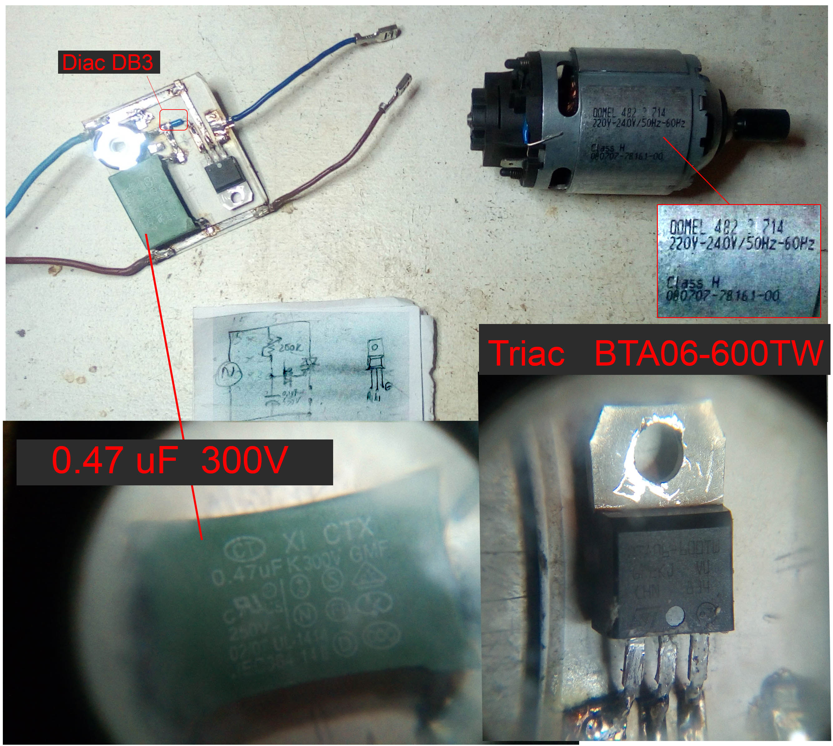
I had a kitchen Hand blender (see image), that I could dismantle.

I took out its motor and electronic board. I tested it and [it was working properly] (with its guts out).
I tin desolder the power wire from the board to get rid of a metal lid on the wire. I solder back the power wire. I test the assemble. Nothing is working. I look stupid. I tested with my electronic voltmeter if the connections are well soldered (between adjacent soldering nodes), and they were ok. I tested (not all) a large majority of components on the board and all looked ok. I look stupid again. I learned to check the triac, and that was good too. (If the gate is connected with A1 but not with A2, is good).(see image of the triac)


I took a electronic schematics from internet for "triac voltage control circuit". (see the image)
I also took all the original electronic components and created with them the new schematic.


I tested it live. My motor started to create a white smog. I unplugged very quickly the power. It is not totally damaged - i hope.
The electronic components are fine.

My biggest mistake is that i didnt use my electronic voltmeter. Lesson learned i suppose.
My best guess, because the 300V of the capacitor, the voltage over the motor was terrible high.
Another guess, is this very Basic and General schematics that i did. Probably I need a more specific skematic with more components. This is my cry for help to you.

And here is my question:
- Can you help me with a better AC motor speed controller using these components that i already have? (and hopefully not damaged too much).
Thank you!
 

tcmtech

Joined Nov 4, 2013
2,867
The capacitor wont change the line voltage to anything higher than it normally is so that's not a issue.

One thing that may be in play is that the more you have may in fact be a DC motor not an full AC motor which if so your triac control system lacks the needed bridge rectifier to convert the AC to DC. If so you can actually cheat on simplifying your speed controller by using a common light dimmer device ahead of the bridge rectifier as the speed controller.

It's just a guess given the design and appearance of the motor, which almost looks like a brushed permanent magnet DC motor would imply that a bridge rectifier may have been in the circuit some place.
 

Thread Starter

q12x

Joined Sep 25, 2015
2,227
This is the original electronic board.(see the image below) There are some empty places because i removed the necessary components from it.
I think you have a very good eye. I did see the 4 diodes that means a bridge rectifier - but at that time i was thinking is probably a fancy or a useless thing. I was sure the motor is AC. Now when you mention it, I remembered this bridge. So its not useless there. Aha. I am not very good at this i suppose. :)
so...
if you zoom in on my previeous image, you can see a skematic there on the table.
Can you draw one for me? Using these components? And adding the necessary ac/dc bridge ? And a led to show that the circuit is on. And give me also some directions since my motor is already a bit fried... i hope is not full fried. I didnt test it yet. I was very upset. The white smoke come from inside of him and he got very hot. Big sparks also inside him. 3-4seconds until I removed the power.


Thread Starter

q12x

Joined Sep 25, 2015
2,227
I checked the motor now. It reads 40ohm on its 2 pins. Unfortunately this is the only thing that I know how to check a motor. I have no idea how to check it more than this. If there are other modalities please share. Sharing is good. :)
I hope this little check i did is helping somehow. Thank you.
 

MaxHeadRoom

Joined Jul 18, 2013
30,572
It looks to me as though it has a wound field, If so,
I'll wager it is a Universal motor, why print 250v 50/60Hz on the outside if it is DC only?
The Hand blenders of this type Are Universal motors, at least the ones I have owned.
These use a triac control readily, sometimes a bridge is added.
All you need to do to confirm it is to lift or otherwise insulate one brush and measure the motor terminal resistance for open circuit.
Max.
 
Last edited:

#12

Joined Nov 30, 2010
18,224
I would like to mention that I ruined a Triac a few days ago because I was not careful enough when bending the leads.:(:oops:
Fortunately, I still had 4 more spares.:)
 

Thread Starter

q12x

Joined Sep 25, 2015
2,227
good practice indeed being careful with too much bending - my pins are already soldered and i will not take it out any time soon. Thanks for the good thought.
Now i will add the ac/dc bridge only. I am scared shirtless.
 

tcmtech

Joined Nov 4, 2013
2,867
I would like to mention that I ruined a Triac a few days ago because I was not careful enough when bending the leads.:(:oops:
If I don't do that to some device at least once a week I feel like I'm doing something wrong. :oops:

Maybe it just me, but lately I feel like the leads on every new device are more brittle than ever before. One good bend and they are done for and I rarely have that problem with old devices I salvage off stuff. :(
 

Thread Starter

q12x

Joined Sep 25, 2015
2,227
good so far? I intend to take out the original diodes. I can see some resistors there too... i wander what they are good for.


#12

Joined Nov 30, 2010
18,224
I feel like the leads on every new device are more brittle than ever before.
"Embrittlement" is a real thing with wire and component leads, but my failure was in breaking a leg loose from the Triac die by cracking the plastic case.
 

tcmtech

Joined Nov 4, 2013
2,867
Embrittlement" is a real thing with wire and component leads, but my failure was in breaking a leg loose from the Triac die by cracking the plastic case.
But the old stuff that should be what's brittle gives me the least problems. It's the brand new components that seem to snap things off right out of the package so easy now. :(
 

Thread Starter

q12x

Joined Sep 25, 2015
2,227
yah, i made the test.
Definitely improved. The sparks were not so BIG and the motor turn more smoothly than on AC before. There are sparks but very tiny - i can see them in interior of the motor. And the motor stays cool for a couple of seconds i made the test. No white smoke. Looks the real deal.
Now, back to the original problem - the triac. When i turn the rezistive pot, it should dim the speed of the motor. Nothing (perceptible) happens.
Any thoughts?
Again, thank you so much for carrying me through this. Its scary playing with 220v. :)
 

Thread Starter

q12x

Joined Sep 25, 2015
2,227
i've observed an interesting thing ... the variable resistor on its contacts that are soldered to circuit, does not read any ohm values (only 0.00). But, i have a 3'd pin out of the circuit, and on that is reading the value. I inverted the potentiometer and exactly the same thing as before. I was happy that i found a problem and i can solve it, but nope, same thing on either side. Its curious. Maybe something from circuit is not allowing the pot to work properly?
The potentiometer is 200k ohm's. (not 250k as in drawing scheme).Close enough.
 

Alec_t

Joined Sep 17, 2013
15,111
the variable resistor on its contacts that are soldered to circuit, does not read any ohm values (only 0.00). But, i have a 3'd pin out of the circuit, and on that is reading the value. I inverted the potentiometer and exactly the same thing as before.
You may have burned out the pot track if you applied power with the pot wiper at one extreme or the other, since there is now no series resistor (other than the motor resistance) to limit the pot current (though if that were the case I would have expected an 'overload' meter reading, rather than '0').
 

MaxHeadRoom

Joined Jul 18, 2013
30,572
A rough indication of the condition of the motor is to run it off of a 12v automotive battery, if it is a series (Universal) motor as suspected, it should wind up pretty good, being a series wound-field motor.
Try in each direction.
There also appears to be a MOV in the circuit, check the visible condition of this, it is blue and labeled ZR11x.
Max.
Max.
 

tcmtech

Joined Nov 4, 2013
2,867
A rough indication of the condition of the motor is to run it off of a 12v automotive battery, if it is a series (Universal) motor as suspected, it should wind up pretty good, being a series wound-field motor.
Try in each direction.
Obviously since he put the bridge rectifier back in that the stock speed control used for a reason and it ran normal, that would confirm it's probably a Permanent Magnet DC motor. ;)

That higher voltage PM DC motor on rectified mains voltage design concept has been around for a long time simply because its one of the cheapest and simplest ways to make a high speed line voltage powered motor system.
 

Thread Starter

q12x

Joined Sep 25, 2015
2,227
You may have burned out the pot track if you applied power with the pot wiper at one extreme or the other, since there is now no series resistor (other than the motor resistance) to limit the pot current (though if that were the case I would have expected an 'overload' meter reading, rather than '0').
to Alec_t :
Well, when I put the power on, everything is working at a somewhat extreme level (at this point, nothing is bringing down the speed of the motor). But is working!!! When i take out the power and test the pins of the pot, it shows 0 on ohmmeter and on diode mode, it Beeps. That track between the too legs of the pot seems to be shorted in interior of the triac. But again, when I power it, is working fine. A bit of brutal speed, but in the parameters.
- Do tell me what to measure (precociously) !!! (And not to burn my voltmeter!) And I will post the result.
Again, thank you. This is fun, while is working, and learning a lot. :)
I am thinking to make some sort of fuse to blow up. To avoid my components being damaged or my cables in my room. I live both of these events with this hellish scheme. Any suggestions are super welcome.
 
Top