Facebook
 Google
 GitHub
 Linkedin
HI all,
I need to offer a 12V output to illuminate a 20mA LED, until a 12V input triggers (something) to make this output 20mA LED turn off. When the 12V trigger input is gone, the LED should turn back on.
I have designed a successful circuit to achieve this, but only using incandescent bulbs in my cars tail lamps, side markers, Headlamp, etc. I used the ground coming through the incandescent car bulbs to triggering (energizing) the BD140 transistors. When the 12v was applied from activating the car's indicators. The BD140 is deactivated, turning off the LED. I have attach the incandescent circuit to this post.
You will also note/see that I have a relay to accept the 0v/Ground trigger from the car's computer for when the 'Check Engine' light is active. I use the N.C. terminals on a relay to power the LED output, until the 0v/Ground trigger from the computer is activated. Once the relay is activated the 12v supplying the LED is removed, turning off the LED when the Check Engine is activated by the car's computer.
I have now replaced ALL my vehicles exterior lamps with LEDs. These new LEDs work fine. BUT ..... now my circuit does NOT. By replacing the incandescent with LEDs, I have removed the Ground triggering the BD140. ... The Check Engine light circuit still works. But I DO NOT want to hear relay clicking, so I do NOT want to use relays to solve this problem.
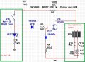
I tried to come up with a solution ... Circuit 2 (attached to this post) works fine for the Check Engine 0v/Ground trigger circuit. But Circuit 3 does not work well. The output in Circuit 3 causes the LED to light up very dim/faded. By lowering the R6 value from 1k to 100ohm, LED6 is very bright. But R6 at 100 ohms heats up within seconds. Once the BD139 is activated.
I am NOT opposed to using MOSfets or Darlington Transistors. I just have many BD139, BD140, 2n3904 and 2n3906.
Thanks
TONY
I need to offer a 12V output to illuminate a 20mA LED, until a 12V input triggers (something) to make this output 20mA LED turn off. When the 12V trigger input is gone, the LED should turn back on.
I have designed a successful circuit to achieve this, but only using incandescent bulbs in my cars tail lamps, side markers, Headlamp, etc. I used the ground coming through the incandescent car bulbs to triggering (energizing) the BD140 transistors. When the 12v was applied from activating the car's indicators. The BD140 is deactivated, turning off the LED. I have attach the incandescent circuit to this post.
You will also note/see that I have a relay to accept the 0v/Ground trigger from the car's computer for when the 'Check Engine' light is active. I use the N.C. terminals on a relay to power the LED output, until the 0v/Ground trigger from the computer is activated. Once the relay is activated the 12v supplying the LED is removed, turning off the LED when the Check Engine is activated by the car's computer.
I have now replaced ALL my vehicles exterior lamps with LEDs. These new LEDs work fine. BUT ..... now my circuit does NOT. By replacing the incandescent with LEDs, I have removed the Ground triggering the BD140.
... The Check Engine light circuit still works. But I DO NOT want to hear relay clicking, so I do NOT want to use relays to solve this problem.I tried to come up with a solution ... Circuit 2 (attached to this post) works fine for the Check Engine 0v/Ground trigger circuit. But Circuit 3 does not work well. The output in Circuit 3 causes the LED to light up very dim/faded. By lowering the R6 value from 1k to 100ohm, LED6 is very bright. But R6 at 100 ohms heats up within seconds. Once the BD139 is activated.
I am NOT opposed to using MOSfets or Darlington Transistors. I just have many BD139, BD140, 2n3904 and 2n3906.
Thanks
TONY
Attachments
-
 221.1 KB Views: 24
 -
 96.4 KB Views: 23
 -
 112.4 KB Views: 21