 Facebook
 Google
 GitHub
 Linkedin
Hey there
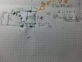
the Exercise questions are:
1)Express all the currents in the circuit using Ib1(given that :hfe=50,Vbe=0.7)
2)find Rb,Given that Vc=10v(and Of course hfe=50,Vbe=0.7,Vc is labeled in the circuit) and Rc=1 kilo-ohm
Well, I have tried to solve the following attached questions but I encountered a few problems :
1)Is my equivalent small signal circuit correct ,more specifically are my currents directed as well?( second picture)? my analysis is based on short circuiting the capacitors and Vcc.
2) If so , what is the meaning of question 2 -- in which circuit should I label Vc=10v,should I still apply small signal model ? is this on the place I marked with hollow dot ?
(if it should be there , something is not correct with my currents since 2551Ib1 goes through Rc and it should be
the exact opposite!!! ) ?
Thanks in advance!
Attachments
-
 1.6 MB Views: 12
 -
 1.8 MB Views: 12


