Transistor in Common Emitter Circuit

Thread Starter

David Waddell

Joined Dec 3, 2014
24
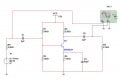
Explain the operation of the transistor in this Commom Emitter circuit with reference to base,collector and emitter currents.
  • Collector Current ic = 800mAdc
  • Gain HFE = 100
  • Collector Base Voltage – 75Vdc
  • Total Power Dispersion – 500mW
Thanks for any help
 

Attachments

MikeML

Joined Oct 2, 2009
5,444
So, if you have simulated it, you should be able to see how it works...

If you want to use a text-book model and use calculations, then show us what you have already tried...
 
[
So what have you done so far in determining those currents?

Do you know how a transistor works?
rutschow, post: 791473, member: 19451"]So what have you done so far in determining those currents?

Do you know how a transistor works?[/QUOTE]
A transistor is an electronic switch that opporates like a valve, there a three pins, the most simple one is an npn transistor ( the order on most is basec collector, and emitter). The base, is where a small signal such as an audio signal from your headphone Jack from your cellphone or other audio source. This controls the voltage between the collector and emitter. Next, the collector, the collector is where the positive rail from your power supply goes in, then your negative goes into the collector. The collector gets your load,( led, speaker, motor, even a relay). Now a small signal transistor uses a very small signal( including, a headphone Jack signal, possibly a microphone, a piezoelectric transducer, even if you just touch the base and emitter pins with your finger).
 

WBahn

Joined Mar 31, 2012
32,823
A transistor is an electronic switch that opporates like a valve, there a three pins, the most simple one is an npn transistor ( the order on most is basec collector, and emitter). The base, is where a small signal such as an audio signal from your headphone Jack from your cellphone or other audio source. This controls the voltage between the collector and emitter. Next, the collector, the collector is where the positive rail from your power supply goes in, then your negative goes into the collector. The collector gets your load,( led, speaker, motor, even a relay). Now a small signal transistor uses a very small signal( including, a headphone Jack signal, possibly a microphone, a piezoelectric transducer, even if you just touch the base and emitter pins with your finger).
This is a rather poor and misleading description of how a transistor works. For instance, the claim that the voltage at the base controls the voltage between the collector and emitter. Whether this even appears to be the case is dependent on the circuitry that the transistor interacts with and not the transistor itself.

The statement, "the collector is where the positive rail from your power supply goes in, then your negative goes into the collector," is nonsensical.

A small-signal transistor does not necessarily use a small signal. In fact, the input signal may be as large or even larger than the output signal.
 

#12

Joined Nov 30, 2010
18,224
Your data in the first post is mostly wrong. It is your job to start figuring out the currents and voltages.
Start with R1 and R3.
 

WBahn

Joined Mar 31, 2012
32,823
Your data in the first post is mostly wrong. It is your job to start figuring out the currents and voltages.
Start with R1 and R3.
What data is wrong. These seem to be straight out of the data sheet, though of course the hfe is given as a specific value instead of a min or a range.
 

WBahn

Joined Mar 31, 2012
32,823
Oops. I thought the data was the specs for this circuit. :oops:
I was wondering that at first, too. It took a bit of head scratching to conclude that it was meant to be datasheet info. The 75V spec was the one that steered be in that direction pretty quickly.
 
Top