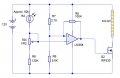
I posted a schematic traced from a commercial outdoor night light about a year ago - if I can find the time, I'll have a look for it.Errr, yes if you say so, but you've lost me. I am but a novice!
Note that the circuit used a photo diode - LDRs have been getting harder to find since RoHS, they contain highly toxic cadmium.Thank you ian field
Interesting but I was also considering trying to design a circuit based around a LM358 and a MOSFET (IRFxxx) instead of fiddling about with transistors.
I shall work on it tomorrow and post it below.
See what you and others think..... to be continued....
Yes, I see the diagram you posted is using a photo diode but I have loads of the GL5528 LDR's which I purchased through AliExpress. They seem to be OK and lots of sellers there are selling them.Note that the circuit used a photo diode - LDRs have been getting harder to find since RoHS, they contain highly toxic cadmium.
I didn't say you couldn't get any - I ordered a couple of bags from China a while back.Yes, I see the diagram you posted is using a photo diode but I have loads of the GL5528 LDR's which I purchased through AliExpress. They seem to be OK and lots of sellers there are selling them.
As I said yesterday, I have designed a circuit to switch on and off a 3528 SMD 12v LED striplight.I was also considering trying to design a circuit based around a LM358 and a MOSFET (IRFxxx) instead of fiddling about with transistors.
I shall work on it tomorrow and post it.

Yes, thank you. This was exactly my thinking. This is also why I chose R7 and R8 values to more or less 'balance' out the voltage at the non-inverting input to about 8v in comparison to the inverting input.With the values of the resistors on the hysteresis setup, your Off Voltage trip will be 8V, when your Ldr is at 60K, the preset needs to be at 24K approx which is around the centre position, looking good to me.
Better to tie non-inverting to ground or the non-inverting input of the other amp, and tie the inverting input to the output.If I tie the unused inputs to ground, would that be suitable?
Thank you, I am still learning. Everyday for everyone is a school dayDecoupling is not a suggestion. It is a universal requirement, which is why it is not mentioned on most datasheets.
0.1 uF and 100 nF are the same thing, so I guess either one will work. For future reference, if the opamp is making more than a few mA output current or is in a full-bandwidth audio circuit, parallel a 0.1 uF ceramic with a 10 uF electrolytic. If the opamp is running on +/- supplies, decouple each supply pin to GND separately.
ak
The circuit includes a high input impedance voltage follower to buffer the tiny photo current of the PD - you can probably leave that bit out if you use a LDR.Yes, I see the diagram you posted is using a photo diode but I have loads of the GL5528 LDR's which I purchased through AliExpress. They seem to be OK and lots of sellers there are selling them.
As I said yesterday, I have designed a circuit to switch on and off a 3528 SMD 12v LED striplight.
I have chucked the idea of using transistors and have come up with this:
View attachment 124106
This is using an LM358 and an IRF530 MOSFET.
I have tested the LDR against the light levels and have noticed that the LDR is about 60k ohms when I want the striplight to turn on so I have tried to design the circuit as close to this theshold as possible.
The R8 100k resistor controls the hysteresis so that the striplight does not flicker when the light levels are close to the switch on/off theshold. If the hysteresis is too close, I can change this value, but I will test it and replace the R8 later if necessary.
VR2 is an trimmer to adjust the theshold switch on/off levels/sensitivity of the theshold values.
I hope it's ok, but I will be anxiously waiting for your thoughts and comments.[/QUOTE
Since R6 and R7 are only used as a reference voltage, you can set their values much higher to reduce drain on the battery. IE 600K each or more for 6 volts.
But why are unused pins of op-amps rarely mentioned on data sheets?Decoupling is not a suggestion. It is a universal requirement, which is why it is not mentioned on most datasheets.
ak
For the same reason they are not mentioned on the datasheets of CMOS digital logic, Pentium processors, and CK722 transistor; another universal law: Except for the ULN2003 and its kind (parts that have input conditioning built-in), never ever leave input pins unconnected.But why are unused pins of op-amps rarely mentioned on data sheets?