 Facebook
 Google
 GitHub
 Linkedin
Hello,
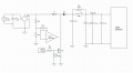
I attach an schematic of a Boost converter circuit that I found on an AC motor driver. The driver takes 110VAC from the grid. So I suppose that the boost converter is used to increase the voltage of the DC Bus to control the 220VAC motor.
The point is that, when the motor has relatively high load, the transistor M1 (which is an IGBT instead of a MOSFET as shown) gets shorted and gate resistor gets open. Sometimes the rectifier bridge also suffers so I have to replace it. The IGBT bridge and recitifier bridge are built-in, that is, all together in a module. The IGBT bridge where the motor is connected doesn't suffer damage. The gate driver is a TC4427. I have replaced the transistor several times, and it still keeps shorting when high load. What could be the problem? It's supposed to stand high loads, so high loads are not the problem.
Attachments
-
 34.7 KB Views: 30
Last edited:


