Transistor, different power supplies, minimal amplification operation

Thread Starter

Kbeezy

Joined Apr 18, 2016
4
Hello,

Here is my goal:

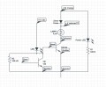
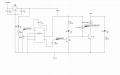
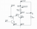
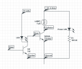
To use a varying DC voltage signal to turn on an incandescent lamp. The input signal is sound from an audio file.

Currently I have three issues:
1. Trying to use a diode to drop a 3 Volt power source down to 2.4 V, which is what the incandescent lamp requires. Yet, I can't get this to work.
2-3. When not using the diode, I can get the lamp to operate. But not only is the lamp not very bright or fairly on when the signal is there, but it doesn't turn off. As well, when the signal is there, the power LED flickers.

Please see my images for the circuits.

The signal comes in and is taken through the base of a TIP 122. On the collector of that transistor, I have an LED which follows the audio envelope of the sound file. I'd like to transfer this signal to an incandescent lamp.

The lamp requires .8 Amp and 2.4 volts.

Issue #1: I've got a 5 volt 2 Amp power supply that I'd like to use. I've read where by using one diode in series with the power supply, the voltage drops 0.6 V. I can't get the lamp to turn on, when the diode is in the circuit

Issue #2: Once the signal isn't present, the lamp is still on.
Issue #3: The lamp is dim.

Any insights are welcome. Thank you for taking the time to read this and consider it.
 

Attachments

dl324

Joined Mar 30, 2015
16,846
Welcome to AAC!

The schematics have problems. When using BJT's, you need to have resistors to limit current into the base of the transistors and through LEDs.

I assume you want the incandescent light to flicker based on the signal level and frequency from the audio input. What is the peak to peak amplitude of the audio signal?
 

wayneh

Joined Sep 9, 2010
17,496
Your diagram raises some questions. But let me first say thanks for providing one!

1. R1 cannot be 100kΩ. Even with a 5V supply, that would allow only ~2V/100k = 20µA of current which would not light an LED.

2. Your diode is labeled as a zener diode, although it is being used as a regular diode. What part is it actually? It might not be able to pass the current you need.

3. As noted, you need base resistors to limit the Base-to-Emitter currents. The minimum value to use is the value that gives a base current of 10% of the desired Collector-Emitter current. So if you want 1A through the bulb, you need at most 0.1A on the base of that transistor. No more, and possibly 10X less.

4. How is your audio signal coupled to the base of the first transistor? That transistor is a Darlington, and so it needs about 1.2V on the base in order to begin to turn on. Ditto for the second TIP122. Since you have a max of 5V, minus the Vf of the LED, on the base of the second Darlington, that might only barely turn it on even when the first TIP122 is approaching "open".
 

Thread Starter

Kbeezy

Joined Apr 18, 2016
4
Thank you for the welcome! I certainly appreciate it.

I do have a resistor on the LED. Pardon my omission earlier. Attached is an updated schematic.

The voltage coming in on the second transistor's (paired with the bulb) base (measuring from the base to the emitter) ranges from:

1.3 Volts (no signal coming in on the base)
1.3 - 1.54 Volts (with a signal coming in on the base)

The light measures:
1.4 Volts (without a signal)
.3 - 1.4 (with a signal)

I have tried to put a pull down resistor of various sizes (47 ohms, 330 ohms, 1k ohms, 100 k ohms) on the emitter and on the collector. This made the light not turn on. I've also tried various resistances in series between the light and the it's power supply, also without the desired changes.

I do appreciate your time and insights.
 

Attachments

Thread Starter

Kbeezy

Joined Apr 18, 2016
4
Thanks Wayneh for your time and questions. Please scroll down

1. I had a type for R1. I was trying out some new software for circuit schematics. R1 is a 330 ohm

2. Good question about the diode. I'm not sure. It has a label - LTH 03 1N4007. I'm not sure if it's a rectifier or a Schottky. I measure .541 V on my diode setting on my multimeter.

3.
As noted, you need base resistors to limit the Base-to-Emitter currents. The minimum value to use is the value that gives a base current of 10% of the desired Collector-Emitter current. So if you want 1A through the bulb, you need at most 0.1A on the base of that transistor. No more, and possibly 10X less.
I will work on this. I'm imagining to put resistors on the base and on the collector in series. Please let me know if there are other configurations to consider.

4. The audio signal is going through a couple of stages of amplification via a few IC's. The last amp (LM 386N-3), which then connects to the base of the TIP, voltage ranges from 1.1 - 1.4 Volts across the base and ground when on. And is at 1.44 Volts when off. I have a 10K pot in the LM 386N-3 which goes between ground, Pin 3 on the LM 386N-3 and the output of my pre-amp, a CD 4049.

Anything else I should be aware of, please let me know. Thanks again for your time!
 

Attachments

dl324

Joined Mar 30, 2015
16,846
Do you have information that makes you believe this circuit will work?

With no input, the first transistor (Q1) will be off. The LED on the collector of Q1 will try to pull the base of the second transistor (Q2) to 3V, but the base is 2 series PN junctions that wants to limit the voltage to 1.4V. With a 5V 2A supply, either the LED or Q2 are going to be damaged.

If you tell us what you want the circuit to do, we can help you with the design.
 

Thread Starter

Kbeezy

Joined Apr 18, 2016
4
I've had the circuit working with one transistor to a tiny incandescent bulb successfully. This time, the bulb is larger and requires more amperage. Attached is the circuit working with one transistor. The tiny lamp is the one that worked successfully, making me think that a larger bulb on a different power supply is also possible.

Currently, without the tiny incandescent bulb there, but with the larger lamp (and required power supply), I can get the lamp to flicker with an audio signal, but it is dim. An additional preamp chip helps (not included in the current diagram). Also when there isn't an audio signal, the light is on just barely. The second transistor runs warm/hot (but not 3rd degree burn hot). As a result, I believe this is possible, but there are errors in my circuit design.

The end goal is to have the incandescent bulb illuminate in accordance with the audio signal - including being off when there is not sound.

Any insights are appreciated! Thanks again for your time and consideration.
 

Attachments

ericgibbs

Joined Jan 29, 2010
18,766
The lamp requires .8 Amp and 2.4 volts
hi K,
Are you aware that the operating current of 0.8 Amp, is when the lamp filament is at its full operating temperature.?
When the filament is 'cold' the inrush current could be as high as 8 Amps, this may cause the power supply to current limit or the final power transistor is unable to sink this inrush current.

If this happens, it's possible the filament will never 'heat' up.

E

If the centre LED has a 100K series resistor it will never 'light' up.
 
Top