Transistor cross over

Thread Starter

Robert Skolnick

Joined Jun 17, 2019
6
hello
i am new to the forum so hope this the correct place for this question.
i am working on the following radio.
Semp AC431 transistorised version. i nrrd the following transistors but cant find replacement numbers here in Brazil. in brazil BC numbers are more common..
2sa234
2sa353
2sb75
ac128
in need 2n or BC replacements for these old resistor.
hope some one can help.
Thank you
Gator
Brasilia Brazil....
 

AlbertHall

Joined Jun 4, 2014
12,624
It may not be quite as simple as that. All those transistors except the 2SB75 are germanium transistors and simply replacing with the silicon versions might well cause problems, with biasing for instance. Base voltage for germanium around 0.3V, for silicon it's around 0.7V.
 

Thread Starter

Robert Skolnick

Joined Jun 17, 2019
6
It may not be quite as simple as that. All those transistors except the 2SB75 are germanium transistors and simply replacing with the silicon versions might well cause problems, with biasing for instance. Base voltage for germanium around 0.3V, for silicon it's around 0.7V.
i understand...would there be a more modern substitute that would be available today for them..this radio is from 1963...what would be a better replacement?

and thanks for the quick answer....
i am lost at this point and can not find these resistors here locally....
 

Thread Starter

Robert Skolnick

Joined Jun 17, 2019
6
Why do you want to replace them - are all the transistors faulty?
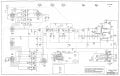
i am confused with this because they seem to be intermittent and are taking turns not working. one minute the mixer they all work and then they fail in random order..i have checked allthe grounds and they seem to be ok.. all the old wax caps have been changed...only the transistors and the resistors are original...can not think ove what else to look at. originally the caps were in bad shape..making lots of hum and no stations would come in...now when it wants to work one station comes in and no others ....i will include a schematic...
the radio is now dead if i inject a signal of 1khz at the beginig of the audio circuit it gos to the speaker with a small distortion.if i inject at the antena ,,455khz i get no output and signal will not trace past the base of the first transistor...
thanks again for the help..
Gator
 

Attachments

KeithWalker

Joined Jul 10, 2017
3,604
i am confused with this because they seem to be intermittent and are taking turns not working. one minute the mixer they all work and then they fail in random order..i have checked allthe grounds and they seem to be ok.. all the old wax caps have been changed...only the transistors and the resistors are original...can not think ove what else to look at. originally the caps were in bad shape..making lots of hum and no stations would come in...now when it wants to work one station comes in and no others ....i will include a schematic...
the radio is now dead if i inject a signal of 1khz at the beginig of the audio circuit it gos to the speaker with a small distortion.if i inject at the antena ,,455khz i get no output and signal will not trace past the base of the first transistor...
thanks again for the help..
Gator
Did you clean the switches? there are a lot of contacts there to go intermittent if they are oxidised or dirty.
You can check the transistors in circuit fairly easily: Measure the voltage between the base and emitter on each one. If it is much above 0.3 volts, the base/emitter junction has failed. If the bas/emitter voltage is very low (<0.2 volts), check the voltage from collector to emitter. If it is low (<0.3 volts) the transistor is shorted.
Be very careful not to short out anything with the meter probes when you make the measurements. Germanium transistors are very easy to damage. I found this out years ago the hard way.
 
I agree with the other posts, the problem is most likely the switches. It could also be the tuning of the circuits but based on your post it appears the transistors are still good.

if i inject at the antena ,,455khz i get no output and signal will not trace past the base of the first transistor...
You are injecting the IF frequency (455KHz) at the wrong location. Inject it at the input to L9, modulated with 1KHz. You may want to disconnect the input to L9 when you do this and also make sure you don't over drive the IF.

If you have a decent oscilloscope you can check the collector of the input transistor and verify the oscillator is operating.
 

MisterBill2

Joined Jan 23, 2018
27,437
Indeed it is not at all likely that transistors are intermittent. They are either OK or out of specifications. Switch contacts certainly are the most likely cause of the problem, and that radio has quite a few of them. And since it is a rotary switch spraying them with contact cleaner, or possibly denatured alcohol, should clean them up and provide better operation.. AND, if the transistors are in sockets, the sockets also will need contact cleaner applied.
 

Zoe123

Joined May 20, 2019
5
It is recommended that you test the transistor inside to determine if it is good. If it is good, you don't need to find a substitute. If it is bad, you can only find a substitute, and there is a capacitor and a resistor inside to see if the surface is damaged. It will definitely be broken), or you can use your hand to touch whether there is a serious heat resistance of the capacitor (the fever is very hot and it is definitely a problem).
It can also be tested with a special LCR instrument that measures resistance.
 

Thread Starter

Robert Skolnick

Joined Jun 17, 2019
6
hello
first thank you for all the help...i found the problem thanks to all your input..
what i found is that the transistors turned out to be ok.
a prior tech changed the resistors form 1/2 watt to 5 watt. in doing so he changed the values of a lot of them. some of them were also cold soldered. i am replacing the resistors with 1 watt(1/2 watt in Brazil is very hard to find.) and also found where L1 and L2 were incorrectly soldered to ground at the caps. All that said... when i finish replacing the resistors i hope the radio will come back to life.
most of the resistors were off by 30 to 40% past tolerance.

i will update when i get them all replaced....
Thanks again for the help...
this is turning out to be a great forum.....
Gator
Brasilia Brazil
 

MisterBill2

Joined Jan 23, 2018
27,437
hello
first thank you for all the help...i found the problem thanks to all your input..
what i found is that the transistors turned out to be ok.
a prior tech changed the resistors form 1/2 watt to 5 watt. in doing so he changed the values of a lot of them. some of them were also cold soldered. i am replacing the resistors with 1 watt(1/2 watt in Brazil is very hard to find.) and also found where L1 and L2 were incorrectly soldered to ground at the caps. All that said... when i finish replacing the resistors i hope the radio will come back to life.
most of the resistors were off by 30 to 40% past tolerance.

i will update when i get them all replaced....
Thanks again for the help...
this is turning out to be a great forum.....
Gator
Brasilia Brazil
Poor soldering and wrong component values were causes that I had not considered. The actual cause is quite different from what my suggestions were based on. Thanks for the explanation.
 

Thread Starter

Robert Skolnick

Joined Jun 17, 2019
6
Note that using a 5W resistor instead of the required 1/2W is not going to have any significance in the performance of the unit.
i figured this but the other tech also changed to different values...none of them are the values in the schematic..they are way off...so i think the values are more the problem than the wattage....
 
Top