Transistor: common emitter

Thread Starter

Zeeus

Joined Apr 17, 2019
616
Hi, beginner here..Trying to understand transistor circuits... 2n3904 not 2n2222

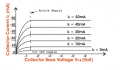
When I used 1.2k for R3 : putting the collector at about 6v, the output looked bad (barn-roof) but with the 3k (collector around 3v) it looked better

I thought it would look better with collector at half it's possible swing (12 to 0.2?)..why not in this circuit?

Gain was about 100 with 3k for R3...Input went about 60mv without noticeable clipping (How to know when it clips?)

Gain approx -Rc/re...for Rc, I did 3k||10k||6k which gives the correct gain...Thinking about it now 3k and 10k are not parallel
 

Attachments

Last edited:

DickCappels

Joined Aug 21, 2008
10,187
Driving a transistor that way, that is without feedback from the collector to the base and without emitter degeneration (a resistor in series with the emitter) will resort in a lot of distortion.

The greater the change in emitter current caused by the signal current through the collector resistor, the greater the distortion.

If you turn your signal generator way down until the signal in the collector is small, say 100 mv peak-peak, then
vary the DC bias on the base so the DC voltage on the collector changed (because of the changing emitter current going through the collector load resistance you will see the input to output gain change.

This happens because the negative feedback from the emitter to base voltage varies greatly with changing emitter current.

One way to reduce this distortion causing effect is to put a small resistance between the emitter and ground.

The emitter resistor reduces and stabilizes the gain of the stage. The gain will be close to the ratio of collector load to emitter resistance.

If you use 10k on the collector and 1k on the emitter your gain will be about 10 provided that your collector voltage is sufficient.
 

Thread Starter

Zeeus

Joined Apr 17, 2019
616
Driving a transistor that way, that is without feedback from the collector to the base and without emitter degeneration (a resistor in series with the emitter) will resort in a lot of distortion.

The greater the change in emitter current caused by the signal current through the collector resistor, the greater the distortion.

If you turn your signal generator way down until the signal in the collector is small, say 100 mv peak-peak, then
vary the DC bias on the base so the DC voltage on the collector changed (because of the changing emitter current going through the collector load resistance you will see the input to output gain change.

This happens because the negative feedback from the emitter to base voltage varies greatly with changing emitter current.

One way to reduce this distortion causing effect is to put a small resistance between the emitter and ground.

The emitter resistor reduces and stabilizes the gain of the stage. The gain will be close to the ratio of collector load to emitter resistance.

If you use 10k on the collector and 1k on the emitter your gain will be about 10 provided that your collector voltage is sufficient.
Thank you....I thought feedback is been applied here because the emitter is fixed and as collector current increases which reduces the collector voltage which is proportional to base voltage..So as collector current increase, base voltage reduces keeping Ic somewhat constant... I thought this

Thank you again..Made me understand better
 

DickCappels

Joined Aug 21, 2008
10,187
You are welcome.

Another little thing is that the collector current is highly dependent upon the base current and most transistors designed for linear operation try to keep the collector current (nearly) independent of collector voltage.
upload_2019-4-30_20-21-7.png
 

Attachments

Top