Transistor Base Resistor Formula

Thread Starter

SILENT001

Joined Jan 14, 2016
35
Good day,

I am trying to figure out how to correctly and accurately calculate the resistor value of a transistor base.

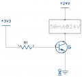
Attached is a simple diagram. What would be the correct formula for calculating R1. Here is the formula I have and calculation using the 2N2222A:

RB = (VCC-VBE)/(IC/B) = (3.3V-1.2V)/(50mA/35) = 2.1V/ 1,42857mA = 2.1V/0.00142857A = 1 470 Ohms

Is my calculation correct? Is my formula correct?
 

Attachments

BobTPH

Joined Jun 5, 2013
8,813
Where did you get 1.2V as the Vbe? That would destroy most transistors, the usual value fis 0.6or 0.7.

And 35 as the current multiplier is also unusual. Most people use 10 for power transistors and 20 for lower power as in this case.

Bob
 

Thread Starter

SILENT001

Joined Jan 14, 2016
35
So here is the datasheet I am looking at 2N2222A Transistor

Current multiplier is here:
1613395709981.png

and Vbe is here:
1613395817828.png

was I suppose to use 0.6 instead of 1.2?

New formula:

RB = (VCC-VBE)/(IC/B) = (3.3V-0.6V)/(50mA/20) = 2.7V/ 2.5mA = 2.7V/0.0025A = 1 080 Ohms
 
Last edited:

BobTPH

Joined Jun 5, 2013
8,813
Those are both the wrong figures to use.

35 is the Hfe at a collector currentof 0.1mA and Vce of 10V. No relation to what you are calculating.

And 1.2 is the saturation Vbe at 150mA, nowhere near your base current.

Look at the very bottom of the chart, the saturation characteristics. This is where you get the current multiplier. They are using 10.

Bob
 

Thread Starter

SILENT001

Joined Jan 14, 2016
35
Those are both the wrong figures to use.

35 is the Hfe at a collector currentof 0.1mA and Vce of 10V. No relation to what you are calculating.

And 1.2 is the saturation Vbe at 150mA, nowhere near your base current.

Look at the very bottom of the chart, the saturation characteristics. This is where you get the current multiplier. They are using 10.

Bob
Thank you very much. Will keep that in mind next time. Appreciate the assistance.

Would the 2N2222A NPN transistor work without a problem for this application or would I need to change the schematic?
 

LvW

Joined Jun 13, 2013
1,752
Would the 2N2222A NPN transistor work without a problem for this application or would I need to change the schematic?
I must admit that I cannot see any application. Is it your goal just to create a collector current?
I suppose, either you want to use the BJT as a switch or as an amplifying device (linear operation)?
In both cases. you need a collector resistor - and for case 2 an emitter resistor (for stabilization purposes)
 

MrChips

Joined Oct 2, 2009
30,720
In the first attempt you determined the base resistor value to be 1.5kΩ.
In a second calculation the value is 1kΩ.
Don't sweat the small stuff.
 

dl324

Joined Mar 30, 2015
16,846
So here is the datasheet I am looking at 2N2222A Transistor
This is from the OnSemi datasheet:
clipimage.jpg
Regardless of collector current they use a beta of 10. This will guarantee that the transistor will be driven into saturation (for a low Vce).

Equations are easier to read if you use Latex.
\( R=\frac{V}{I}=\frac{3.3V-0.7V}{5mA}=520\Omega\)

EDIT: use image with device number
EDIT2: Corrected base current. Should have been 5mA instead of 2mA.
 
Last edited:

MrChips

Joined Oct 2, 2009
30,720
More votes are coming in.

Here is why you don't sweat the small stuff.
Let's assume you don't know exact values of Vbe and beta to use.
We will use some worse case figures,
Vbe = 0V and 0.7V
Ib = 2mA and 2.5mA

Rmax = 3.3V / 2mA = 1.65kΩ
Rmin = 2.6V/2.5mA = 1kΩ

Take your pick or any value in between.

Edit: Extreme worse case would be:
Rlow = 2.5V / 5mA = 500Ω
 

Thread Starter

SILENT001

Joined Jan 14, 2016
35
I must admit that I cannot see any application. Is it your goal just to create a collector current?
I suppose, either you want to use the BJT as a switch or as an amplifying device (linear operation)?
In both cases. you need a collector resistor - and for case 2 an emitter resistor (for stabilization purposes)
I intend on using it as a switch hence the 3.3V driving the transistor for a 24V load. The load is some electronic boards that according to the lab bench power supply draw a maximum of 35mA at idle and 50mA depending on what the unit is doing. The units require 24V to power on.
 

MrChips

Joined Oct 2, 2009
30,720
I intend on using it as a switch hence the 3.3V driving the transistor for a 24V load. The load is some electronic boards that according to the lab bench power supply draw a maximum of 35mA at idle and 50mA depending on what the unit is doing. The units require 24V to power on.
Aha! That situation calls for a different solution. You either can use a high-side switch or a relay.
 

ElectricSpidey

Joined Dec 2, 2017
2,758
Another thing to consider, and most people don't is just how far into saturation is needed.

For example if available base current is limited, but losing a little voltage is acceptable one might want to run the transistor just out of saturation.
 

Thread Starter

SILENT001

Joined Jan 14, 2016
35
Aha! That situation calls for a different solution. You either can use a high-side switch or a relay.
High side switching would require two transistors as I am driving the transistor from a MCU that has 3.3V High or Low output and I am terrible at using PNP transistors
 

BobTPH

Joined Jun 5, 2013
8,813
The problem with switching ground on electronic circuits is that it leaves no reference for inputs and outputs that are connected to other powered parts of the circuit.

Bob
 

dl324

Joined Mar 30, 2015
16,846
I corrected the base current value I used in post #10. For some reason I thought the load current was 20mA, not 50mA. The equation now uses 5mA for base current.
 
Top