Transformers

Thread Starter

RAMBO999

Joined Feb 26, 2018
259
Hi everyone

Hope you are all doing ok in these difficult times.

Keep busy and stay clean.

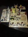
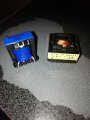
Anyway, I have pulled a couple of random transformers from old power adapters (see attached image).

I want to mount them on a pcb and have a play around with them.

I have searched the internet using the markings on them to see if I can find a datasheet or any kind of
pin information on them at all with no luck.

Does anyone know where I can find this information?

Is there a generic datasheet or something?

Thanks
 

Attachments

KeithWalker

Joined Jul 10, 2017
3,607
I am assuming that the transformers have laminated iron cores, not ferrite. If they are ferrite, this information does not apply. Most of the information about the transformers is shown on the cases of the power adapters that you took them from. The information will give you the primary voltage and the secondary current. If the supplies were un-regulated, the approximate output voltage will also be given. If they were regulated, the secondary voltage can be measured if you connect the primary to an appropriate mains supply. The primary winding will be the one that has the highest resistance. Take the necessary precautions when you do this by Insulating the high voltage connections to the power cord and do not touch them while you are making measurements on the secondary.
I hope this information is helpful. Good luck with your projects.
Keith
 
Last edited:

LesJones

Joined Jan 8, 2017
4,511
I also think they look like they are from SMPSs. The left hand one looks like one winding has several wires in parallel to reduce skin effect. Skin effect would not be significant at 50 or 60 hz. They will be of no use to you.

Les.
 

Thread Starter

RAMBO999

Joined Feb 26, 2018
259
I am assuming that the transformers have laminated iron cores, not ferrite. If they are ferrite, this information does not apply. Most of the information about the transformers is shown on the cases of the power adapters that you took them from. The information will give you the primary voltage and the secondary current. If the supplies were un-regulated, the approximate output voltage will also be given. If they were regulated, the secondary voltage can be measured if you connect the primary to an appropriate mains supply. The primary winding will be the one that has the highest resistance. Take the necessary precautions when you do this by Insulating the high voltage connections to the power cord and do not touch them while you are making measurements on the secondary.
I hope this information is helpful. Good luck with your projects.
Keith
Thanks Keith

There are 6 pins on one side and 5 pins on the other on each. It's info on those pin connections that I am looking for so than anything else. Does the primary always have more coils than the secondary hence the higher resistance? What if the primary consists of more than one coil? Is that possible?
 

MrChips

Joined Oct 2, 2009
34,809
There are 6 pins on one side and 5 pins on the other on each. It's info on those pin connections that I am looking for so than anything else. Does the primary always have more coils than the secondary hence the higher resistance? What if the primary consists of more than one coil? Is that possible?
As suggested, these are not your standard AC mains transformers. These are high frequency pulse transformers used in SMPS.
 

ronsimpson

Joined Oct 7, 2019
4,691
Thanks. I will need to look up that distinction up.
This transformer; input is 120vac 60hz. (or 220vac) or (50hz). Lives in the power line. The metal core is make of sheets. This type is also probably good up to 400hz.
1586011327689.png
This is more like what you have. Made to work at 100khz. (50khz to 500khz) Note the core is very different. Will not be happy on the power line at 60hz.
1586011582066.png
In you house there is 50/60hz transformers. In old airplanes they used 400hz because the transformers are much smaller/lighter. In switching power supplies the frequency going through the transformer is much much faster so smaller transformers can be used.
 

Tonyr1084

Joined Sep 24, 2015
9,744
You MIGHT find a use for them as an audio transformer since audio signals average 10KHz. Human hearing range is typically 20Hz to 20KHz. Those transformers won't do much with low frequencies, but voice, lead guitar and anything else midrange and up should do something. And by something I mean I have no idea what they can be used for. But as for power supplies - you will need high frequency and pretty much the boards they came out of. But as stand alone transformers - they're not going to do you any good on house voltages.

If I were going to mess around with those transformers I'd start with a transformer I KNOW what it's doing. 120 to 12 volts AC. Then I'd use the 12 volts AC and connect them to whatever lead seems most appropriate and see what I get on the rest of the pins. Lots of testing and taking notes. And you're working with a low voltage to begin with so you're not running TOO much danger. But there's always a chance you could find some pins with 120 VAC output. EXTREME CAUTION IS RECOMMENDED.

Stay healthy.
 

Thread Starter

RAMBO999

Joined Feb 26, 2018
259
You MIGHT find a use for them as an audio transformer since audio signals average 10KHz. Human hearing range is typically 20Hz to 20KHz. Those transformers won't do much with low frequencies, but voice, lead guitar and anything else midrange and up should do something. And by something I mean I have no idea what they can be used for. But as for power supplies - you will need high frequency and pretty much the boards they came out of. But as stand alone transformers - they're not going to do you any good on house voltages.

If I were going to mess around with those transformers I'd start with a transformer I KNOW what it's doing. 120 to 12 volts AC. Then I'd use the 12 volts AC and connect them to whatever lead seems most appropriate and see what I get on the rest of the pins. Lots of testing and taking notes. And you're working with a low voltage to begin with so you're not running TOO much danger. But there's always a chance you could find some pins with 120 VAC output. EXTREME CAUTION IS RECOMMENDED.

Stay healthy.
That's why I want the datasheets. So I know what they are doing and test accordingly. It's the pins as well that I need to figure out.
 

dendad

Joined Feb 20, 2016
4,637
You will probably not find any data sheets as switch mode transformers are usually custom made for the application, not across the counter types.
The numbers will be in house designations.
What actually do you want to do with transformers anyway?
If you just want to see how they work, I reckon you start off with a mains to 10VAC transformer for example, that is already terminated, like in an old plug pack, not a DC out one, and run that low voltage AC into other small transformers that you want to play with.
And it may be worth adding a series resettable fuse (Polyswitch) or a lamp in series just to protect from shorts.

As for the SMPS transformers you have shown, by all means have a play, but be careful as that will have high voltage on them in normal operation, quite easy to "electroplate" yourself!
 

ebeowulf17

Joined Aug 12, 2014
3,307
I have searched the internet using the markings on them to see if I can find a datasheet or any kind of
pin information on them at all with no luck.
The numbers will be in house designations.
I've also seen transformers marked with the part number and/or specs for the power supply it was built into. Caused all sorts of regulatory headaches for us because officials from other countries see what appears to be a part number on a transformer and insist that we provide regulatory and compliance data on a transformer with that part number, when in fact the part number is for the entire SMPS module. Even when we provide datasheets, sales orders, etc. to prove it, they continue to fight us. It's insane.

Anyway, point being that the numbers on the transformer might not even have anything to do with the transformer at all - the transformer might just be a convenient place for them to put markings for the whole unit that you stole the transformer from!
 

Thread Starter

RAMBO999

Joined Feb 26, 2018
259
Thanks for the info everyone. The key bit of information is the SMPS bit. RS do a range of stock SMPS transformers that come with datasheets and they are really quite cheap. So I am going to buy a couple of those and use them to check out how they work and then use that knowledge to figure out how the ones that I have work. They shouldn't be too different.
 

Dodgydave

Joined Jun 22, 2012
11,395
Don't bother buying them, they will be no use to you, you're better off reading up on how atx psus work and switchmode psus.
 
Top