Transformer sag, non linear, and, voltage too high for 3-terminal regulators?

Thread Starter

Hamlet

Joined Jun 10, 2015
519
I have noticed something at my workbench, am I close?
When using a mains power transformer, I have noticed
that they all sag under load. Some are worse than others,
this we all know. However, it seems to me that, for instance,
a transformer RATED for 3A @24v, the unloaded voltage (30v) will sag
less as a greater load is introduced. I might get a 4v sag
with the first .25A load, but only a 6v sag with a 3A load, just as an example.
Am I seeing this correctly?

In the aforementioned transformer example, a 24v AC secondary
will be over 42v rectified & filtered. This is still a little high for
an LM317, and way over the top for an LM338.

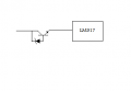
Is there a way to deliberately introduce a little voltage sag before the LM317/LM350/LM338?
Perhaps a small bulb or resister either just before, or just after the bridge?

How does one solve this problem when the voltage is just a little too high?

This application/project is just for small bench-top power supplies, and little projects around
the home and shop, either fixed voltage, or variable.
 

#12

Joined Nov 30, 2010
18,224
Yes. The completely unloaded voltage floats high because the rectifiers eventually arrive at nearly zero volts across them as your first capacitor charges up...among other things arriving at zero volts of loss due to very little current flowing. The power companies have been increasing the delivered voltage across the last 40 years, too.

The rating of a transformer is: At the labeled power line voltage AND the rated load. That's where the rubber meets the road. If you add a resistor in series with no load, it won't fix anything. Try a pre-load of a few percent of the rated maximum. If that doesn't drag it down enough, maybe a zener diode AND a pre-load. There is also an HV version of the regulator chips rated for 60 volts.
 

gerty

Joined Aug 30, 2007
1,305
Check this out to see if your rectifier type (full/half/bridge) is having an effect on your current. With those formulas maybe you can see where your problem lies.
 

Attachments

Thread Starter

Hamlet

Joined Jun 10, 2015
519
Gerty, I found your doc a couple weeks ago. I've been all over it since.
I did all the calcs, and wired up the examples as experimental circuits on
my workbench. I noted that the last circuit on the Hammond Transformer document
the one with choke made little difference...

upload_2015-9-9_12-36-23.png
Except for the resistance in the coil, little difference to the circuit, with or without choke,
& the choke did not increase amps, no, nothing, nada "ID.C. = 0.94XSecdary I A.C."
The choke I used was a 12v/10A transformer.
It should have been large enough, I would think.
I was totally disappointed, as that would have dropped my output
voltage, and bumped my amps, helping to dampen the overall sag.
I felt like that direction was just more uphill battle, so I dropped it.

#12, I did not mean using a resistor in series, but rather, across the AC line
on the secondary, or perhaps after the bridge & caps. I didn't have a wirewound large enough
to work as a preload to burn off more than one volt. I did use a small light bulb,
or rather, two 12v, .25A bulbs in series.

Apart from the resistor or lamp idea, maybe I could use a couple of power transistors
with a zener, to drop 7 or 8v just after the caps, but before the LM338? A kind of pre-
regulator?
 

#12

Joined Nov 30, 2010
18,224
The choke method depends on continuous current to work. Not applicable to this case.
So we see that a quarter of an amp will not knock the DC voltage down to the 35 volt limit of the LM338.
Yes, you can add a pre-regulator using a zener and a transistor.
Why do you say, "a couple" of transistors?
What is your real intent? Dual voltages?
Did you look at the transformer PDF and see that you can not get 3 amps DC out of a 3 amp AC rated transformer? If you're going to split this for a +/- supply, you might find the current limitations of the transformer are low enough to use the chips that will handle 60 volts. I think they go to 1.5 amps each.
 

Thread Starter

Hamlet

Joined Jun 10, 2015
519
Okay, back from the workbench, fooling around with a zener & TIP102 darlington NPN.
It works, sort of...

Well, everywhere I read, you gotta keep the power dissipation on your bjt lower than the datasheet, 30w or so.
I figure share it with two, and be safe. I'm not ready to build a dual supply. I tried it with a single TIP102,
and nothing got hot with 1.66A load, so I guess one is okay.

I just ordered another dozen LM317. I guess I should have got LM317HVT.
Because I don't have those today, I will try something else. Does anyone
have a simple pre regulator circuit I can use? I have 2 each of the 9v, 10, 12v,
13v zener, & 4 each of 18v zeners, all 1w, several different Darlingtons, TIP3055s...
 

crutschow

Joined Mar 14, 2008
34,452
You can drop voltage with a zener and a NPN power transistor (such as the 3055).
Just connect the zener between collector and base (zener cathode to collector).
Then connect the collector to the filter output, with the emitter to the LM317 input.
The voltage drop will be approximately equal to the zener voltage plus the base-emitter voltage (0.7V).
It acts similar to a power zener diode.
 

#12

Joined Nov 30, 2010
18,224
I've never done this before, but it looks simple. The collector can have all the current it wants, as long as it's (zener) volts above the base. Annnd...crutschow described it.
 

Attachments

Thread Starter

Hamlet

Joined Jun 10, 2015
519
Is it really that seriously simple? I've been looking for something like this FOREVER!
XOXOXO to crutschow!!! I've googled "power zener" and this and that, but have
never seen it.

I'm going to series two 18v zeners and try this right now and shave a few volts off the top.
I love it!
 

#12

Joined Nov 30, 2010
18,224
XOXOXO to crutschow!!!
Hey, I got there, too!
I was 20 seconds behind crutschow because I was making a drawing for you. (Whine. :()
(Click on the, "like" button, it's the only pay we get.)

Watch your power dissipation levels. You can't pick off 36 volts with the pre-regulator without getting into heat considerations. For whatever current happens, 42 volts times I = power, and the two regulators have to share that. 120 watts is a lot to get rid of! even with two devices to share the heat. For that matter, you can't pick off 36 volts and have anything left for the voltage regulator chip! This isn't a voltage sharing circuit, it's a voltage shaving circuit. Whatever amount of volts you waste in the pre-regulator, they are not available for the voltage regulator.

Seriously, when you invest 40 or 50 years into this, you sometimes find a problem that needs a very simple solution. This one was fun. :p
 
Last edited:

Thread Starter

Hamlet

Joined Jun 10, 2015
519
Okay guys, likes all around!

I was thinking two 18v zeners, um, like a simple voltage regulator I mentioned that I was working with in post #6, but this is a little different.
As you say, a voltage shaver, as it were. I'll post later when I get it lashed up. Thanks for helping me iron this out.
 

Thread Starter

Hamlet

Joined Jun 10, 2015
519
Bench top testing of the "voltage shaver":

Using a TIP3055 & 5.6v zener, I was able to drop a handful of volts.

Curious about how much voltage I could dissipate, I swapped the
5.6v zener for a 1w, 18v zener. The 3055 got a little warmer, but the
zener got hot running 1.66A. I then swapped in a darlington TIP102, and
the zener ran cool. Then, & paralleled 3 darlingtons with 0.1 ohm
3w resistors on the emitters. All these were mounted on a surplus
CPU heatsink, drilled & tapped for the To-220 devices, wired dead bug
style. Applying a 4A load (halogen lamp) the zener was still cool after
several minutes, but the heatsink got hot! I raised the fan/heatsink/transistor
assembly off the workbench with little blocks, energized the fan, and
it initially blasted heat out like a hair dryer. I let it run for an hour like
this, and the transistors never got so hot that I could not comfortably keep
a finger on them, and the heatsink cooled off nicely in the airstream. I figure
that's about 80watts.

I think I'll keep this heatsink/darlington lash-up, and use it for the final output for a LM723 based power supply.
(I'll assemble a smaller heatsink for the "voltage shaver" per original discussion.)

There is room on this large CPU heatsink for 3 more darlingtons, so it could drive perhaps 10A
before running out of dissipation capacity. I tapped it with six holes, so easy enough at this
stage.

I recall the LM723 has a final output of 150mA, which might be enough to drive such an
arrangement???? Perhaps a TIP142 could be better? I seem to recall that device has better
hfe..
 
Top